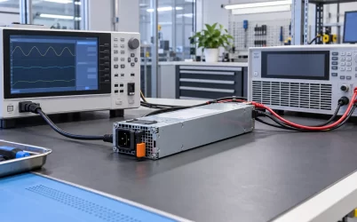
A server can contain two functioning power supplies and still be configured without meaningful power redundancy. The host must have enough surviving capacity for its permitted load, its power-management policy must be set to a supported redundant mode, and the supplies must be connected to the intended upstream feeds. For a typical two-module 1+1 arrangement, one module can be lost while the remaining module continues to power the approved server configuration. Installing the second cartridge is only the physical beginning; the server’s reported mode and the actual cord paths reveal whether the intended protection exists.
First identify what the platform is configured to protect
“Redundant power” can describe different failures. Module redundancy protects against one PSU cartridge becoming unavailable. Feed redundancy protects against loss of one upstream circuit, rack PDU, or other defined source. A server with two modules connected to the same PDU may retain module protection while remaining exposed to that PDU’s failure. Conversely, separate A and B feeds do not create module redundancy if the server relies on both supplies to sustain its current load. State the protected event before touching a management setting.
The policy names vary by vendor and generation. A platform may offer N+1, 1+1, grid, combined-capacity, or nonredundant modes; another may expose only a status indication rather than an operator-selectable mode. Do not treat these labels as interchangeable across management interfaces. In the Lenovo XClarity Controller 3 documentation, power-redundancy settings describe how the server handles the loss of a PSU; its nonredundant mode does not guarantee continued operation after that loss. This is a vendor-specific example of why a software-reported state needs interpretation, not a universal definition of every BMC setting.
Begin with the exact server model, supported PSU population, firmware documentation, and approved module pairing. Some hosts require matching modules or a particular bay population. Others may impose power caps or different behaviors when input voltages differ. Those conditions come from the platform, not from a generic CRPS label. If the BMC reports a redundancy mode that the documentation does not explain for this chassis, do not guess its failure boundary from the name alone.
The arithmetic behind a 1+1 setting
In a two-module 1+1 configuration, the protected load must fit within the supported output of one surviving module and the entire surviving distribution path. Adding two nameplate ratings can misstate usable protected capacity. If two hypothetical 1,200 W modules feed a server whose approved sustained demand is 950 W, the load might remain serviceable after losing either module—provided the modules, input source, thermal conditions, PDB, and host policy support at least that demand. A 1,350 W server load would not be protected by one 1,200 W module merely because the pair is labeled 2,400 W in aggregate.
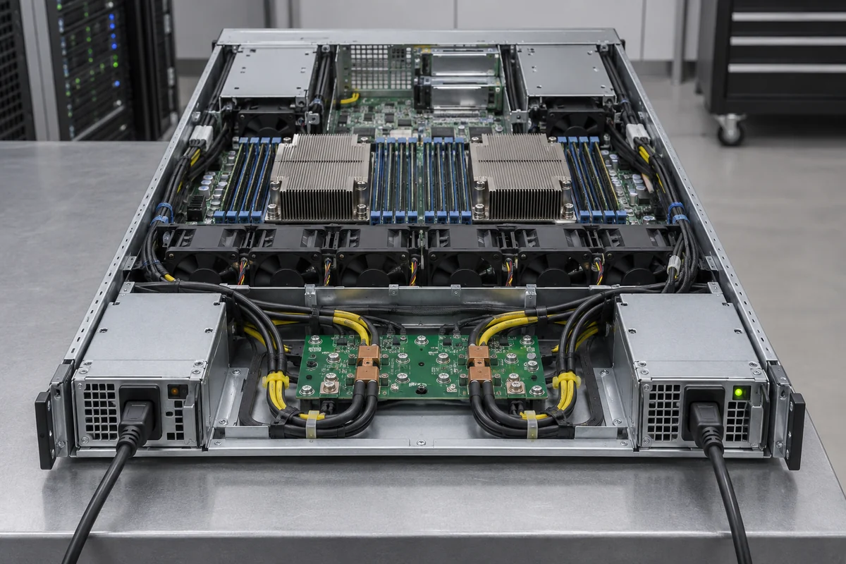
The useful load figure is not a single idle reading. Consider the permitted processor and accelerator population, memory, drives, fan behavior, boot and storage events, and the management policy that might throttle the host after a power-path loss. A host may intentionally reduce performance to remain inside the surviving module’s limit. That can preserve availability but not necessarily the same throughput. The configuration decision must therefore distinguish “stays powered” from “sustains the full workload.”
The PSU’s usable rating may depend on AC input voltage and inlet temperature. If a module only offers a stated high output at a higher line voltage, a 1+1 claim based on that figure may not hold on a lower-voltage feed. Likewise, if a PSU is derated for the actual inlet condition, the protected capacity shrinks. The BMC may know the installed PSU part numbers yet not account for every field constraint. Compare its reported available power with the model’s published limits at the deployment conditions rather than assuming the display is an unconditional guarantee.
A larger N+1 system follows the same failure-state logic: after the specified one module is removed, the remaining modules and distribution path must support the allowed load. It need not be literally one spare cartridge idling unused. The host may share current across all installed modules. Redundancy describes the capacity left after failure, not a fixed duty cycle during normal operation. The server redundant power supply selection overview discusses the underlying module and capacity choices; configuration adds the platform policy and feed map that make the selected assembly operate as intended.
Trace both cords before trusting an A/B label
For dual-feed protection, each PSU’s cord should terminate on the intended independent source path. A neat rack can conceal a common point: two differently colored cords might enter different outlets on the same PDU, or two PDUs might ultimately share one breaker or UPS maintenance domain. The server cannot infer this topology from its rear connectors. Its management interface can report that both PSUs see input, but usually cannot prove that the facility paths are independent.

Create a physical map from PSU bay to cord, rack PDU outlet, branch circuit, UPS or other upstream source as appropriate to the site’s availability requirement. The map is not busywork: it defines what a single failure can remove. If both modules are fed from one source, set expectations accordingly. Module-level redundancy may still be valuable, but calling it A/B feed redundancy would be misleading.
The input cords and outlets also need to support the surviving state. If one module fails, the remaining supply and its AC path may carry substantially more current. A deployment with two healthy PSUs drawing modest current on each feed can still be unsuitable if either remaining feed cannot support the post-failure demand. Review the exact module’s input rating, power-cord type, outlet, rack PDU, branch circuit, and applicable electrical requirements. Do not size the path by dividing normal power evenly between two cords and stopping there.
During rack changes, preserve the map. An operator may move a cord to a convenient socket while servicing a PDU and silently collapse two independent paths into one. The BMC will still see two powered PSUs, so a healthy status icon cannot detect the upstream mistake. Label each path in a way that corresponds to actual infrastructure records, and update those records when a feed or outlet changes.
What the management interface can and cannot tell you
The BMC can often report PSU presence, input state, output state, fault alarms, installed power capacity, redundancy state, and sometimes individual input or output power. Which fields exist and what they mean depend on the host and PSU integration. For example, “redundancy lost” after one module is unplugged may be the correct warning while the server continues operating on its surviving path; it is not necessarily evidence that the transfer failed. Conversely, “both supplies present” is not proof that a defined one-module failure is survivable.

Record the baseline state while both feeds are healthy: recognized module identities, firmware or hardware revisions if shown, active policy, available and required power, relevant power cap, and alarm status. The point is not to create a generic certification package; it is to understand what this host actually reports so a later change can be interpreted. If one module appears as unknown or incompatible, resolve that before treating the pair as protected, even if its fan spins and an indicator illuminates.
Be careful with power-saving policies. Some platforms can place one supply in a lower-activity state to improve efficiency under light load while retaining a supported failover behavior. Others may offer a combined-capacity mode that uses both modules to support a larger load but forfeits one-module survival. A setting that reduces apparent energy consumption is not automatically the right availability configuration. Read the model’s policy description and confirm the service-level requirement before enabling or disabling it.
Telemetry also has a boundary. A PSU output reading may describe power delivered from one module, while rack PDU metering describes AC input to its outlets. These numbers differ because of conversion loss and measurement location. If a power-policy change appears to “save” a large amount, establish that the two measurements include the same equipment and workload. A change in CPU activity or fan speed can overwhelm a small PSU-efficiency difference.
Configure in an order that does not create an avoidable outage
For an existing production server, start by obtaining the model-specific service and management instructions. Verify the proposed modules and bay population, then document the current BMC policy and both cord destinations. Review the server’s allowable load and any cap or degraded-performance behavior. Only then change a redundant/nonredundant setting through the supported management interface. Some policy changes may require a restart or may be rejected when the installed modules cannot support the requested mode; follow the platform’s actual instructions rather than assuming a universal sequence.
Changing the BMC label does not repair a physical deficit. If the host does not have enough capacity after a module is lost, the safe options are to reduce its allowed configuration or load, install a platform-approved higher-capacity assembly, or accept and document a nonredundant operating state. Never force a control setting to show “redundant” while the supported one-module capacity is below the permitted load. Software cannot increase a PSU’s electrical rating or the PDB’s current capacity.
A maintenance rehearsal should reflect the failure the configuration promises to survive, but it must be performed under the host manufacturer’s procedure and the site’s change controls. Observe the server’s status and workload while one intended path is unavailable, then restore it and confirm normal redundancy returns. For a system fed from A and B infrastructure, a PSU-module removal checks a different boundary from a controlled feed interruption. Do not substitute one result for the other, and do not unplug a production feed casually to satisfy an article’s checklist.
After a PSU replacement, confirm that the new module is recognized as an approved part and that the configured mode returns to its intended state. A replacement can be mechanically seated while the BMC still reports incompatible inventory, a missing input, or reduced power budget. Review the alerts and the actual cord path before closing the service event. The point of redundancy is not merely to survive the first fault; it is to return to a protected state after repair.
Three states a dual-PSU server may pass through
Consider a server initially configured for 1+1 operation with two approved modules on independent A and B feeds. Both modules are recognized, one-module capacity covers the permitted workload, and the BMC reports a healthy redundant state. If the A-side module loses input, the host remains powered by B, while the redundancy indicator changes to degraded or lost. The server has fulfilled the one-path continuity objective for that event, but it is now exposed to another B-side loss until A is restored.
If the replacement A-side module is inserted but connected to the same B-side PDU, the BMC may again report two healthy PSUs. Module redundancy may have returned, yet the original A/B feed protection has not. The physical cord map is necessary to recognize the difference. Reconnecting A to the intended source and confirming normal status restores the full defined configuration.
Finally, imagine an approved workload expansion that pushes permitted demand beyond one module’s supported output. The server might still run normally with both supplies, but the original 1+1 promise is no longer valid. A BMC warning or enforced cap may make the change obvious; absence of an alarm should not be interpreted as proof. The configuration is a relationship among installed capacity, allowed load, management policy, and feed topology. Once any of those changes, the redundancy claim must be reevaluated for the actual server—not for a generic two-PSU diagram.