A control cabinet can contain two devices labeled “constant current” that perform very different jobs. One regulates current accurately through a process load. Another is a voltage supply whose overload protection limits current after the output voltage collapses. Treating those descriptions as interchangeable can leave a controller restarting, an LED string underdriven, or a process operating outside its intended range.
The useful distinction in constant voltage vs constant current in industrial power supplies is the variable the source regulates during normal operation. A constant voltage supply maintains an output voltage while the load determines current. A constant current supply maintains output current while the required voltage changes within its supported range. Some supplies support both operating regions, but a protection feature alone does not establish a continuous, accurate current source.
The controlled variable follows the load’s job
Constant voltage, or CV, suits equipment designed around an input voltage range: industrial computers, control electronics, communications devices, and many actuator drivers. The supply attempts to keep its output near the voltage setting as demand changes. A current rating describes available capacity under stated conditions; it does not mean that the supply forces that current through every connected device.
A hypothetical 24 V controller drawing 2 A does not receive 10 A simply because its source is rated for 10 A. Its input circuitry establishes the operating current. The source can support additional demand within its ratings, while wiring and branch protection still need appropriate coordination. Replacing an undersized source with a higher current rating can solve a capacity problem, but does not correct an incorrect voltage setting.
Constant current, or CC, is useful when current is the process variable. Examples include a suitably specified LED driver feeding a bare LED string or a dedicated process supply regulating current through an electrochemical load. As the load changes, the source adjusts voltage to preserve the current setting. That adjustment has limits: a current source cannot maintain its setting through any arbitrary load or wiring condition.
The equipment boundary matters. An LED fixture containing its own driver may require a CV input even though its internal LEDs need controlled current. A motor drive generally accepts a DC voltage bus and regulates winding current internally. Supplying either device with a current source because the final physical process involves current can interfere with the electronics responsible for that process.
How a dual-mode supply crosses from CV to CC
For a supply designed for CV/CC operation, the voltage setting and current setting define a boundary between operating regions. With a simple resistive load, current in CV operation is I = V/R. If the resistance falls until that calculated current reaches the current setting, the supply reaches crossover. Beyond that point, current regulation can take over and output voltage falls as resistance decreases.
Consider an idealized source set to 24 V with a 5 A current setting. A 12 ohm resistor draws 2 A, so the source operates in CV. At 4.8 ohms, the operating point reaches 24 V and 5 A. With a 3 ohm resistor, an ideal CV/CC source maintains 5 A at 15 V. These are illustrative steady-state calculations, not specifications for an industrial product.
The example also explains why setting two numbers does not compel both to be delivered simultaneously. A passive load has its own current-voltage relationship. The supply holds one regulated quantity while the other follows that relationship, subject to its operating envelope. A programmable voltage ceiling becomes a compliance limit during CC operation; if the load needs more voltage, the requested current cannot be maintained.
Real equipment adds output-power limits, minimum regulated voltage, adjustment restrictions, and dynamic behavior. Some programmable supplies offer a rectangular output envelope; others permit different voltage-current combinations within a power boundary. Read the operating-area description rather than assuming that maximum voltage and maximum current are simultaneously available. Resistance calculations also do not describe the startup of an electronic load or the changing forward voltage of an LED string.
Why “constant current limiting” needs a second reading
Industrial voltage supplies often specify an overload response rather than a user-controlled CC operating mode. A constant current limit reduces voltage while holding current near a protection threshold. Foldback reduces available current as voltage falls. Hiccup operation periodically interrupts and retries the output; shutdown removes output until the documented recovery condition is met. These responses can produce very different results with the same nominal load.
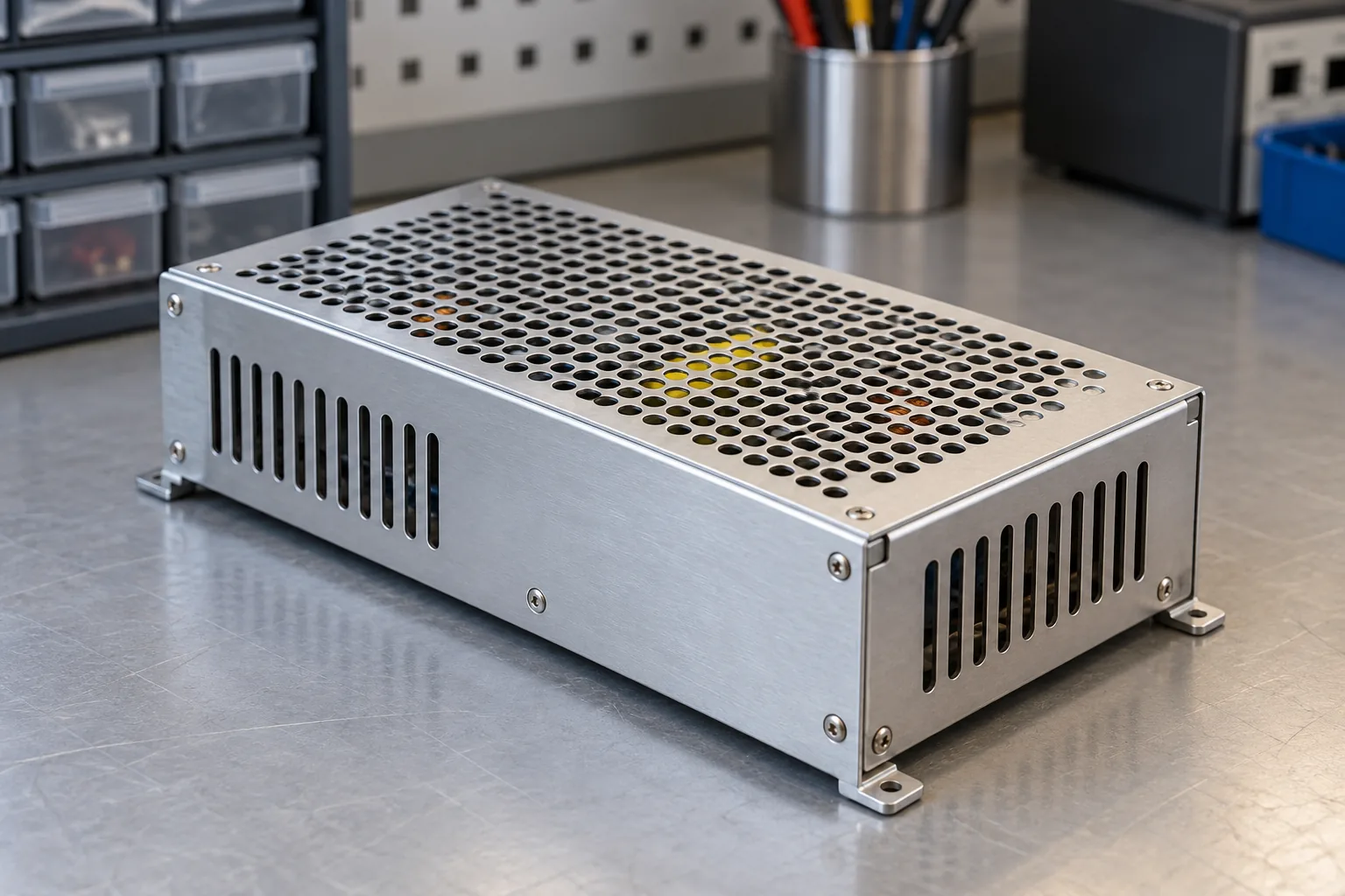
One documented example is the MEAN WELL RSP-500-24. Its family datasheet lists constant current limiting with automatic recovery after the fault is removed. That statement describes its overload protection; it does not, by itself, establish an adjustable process-current setting or precision CC performance. The manufacturer’s RSP-500 specification separates the normal output specifications from the protection description.
A usable CC process specification needs more information: the current adjustment range, accuracy, ripple, load regulation, voltage compliance range, and permission to operate continuously in that region. A broad overload threshold is a different specification from a tightly controlled current setpoint. Likewise, automatic recovery tells you what happens after a fault clears; it does not describe current stability while a process runs.
Some designs combine behaviors, such as current limiting followed by shutdown after a delay. A short-circuit response may also differ from the response to a moderate overload. Consequently, “has OCP” is too vague to predict startup or sustained loading. The exact model’s protection curve, timing description, and operating instructions carry more useful information than the generic protection acronym.
Nor does a CC operating indicator establish measurement accuracy. A source can be regulating current while its displayed value has a different tolerance from its actual output specification. If process quality depends on delivered current, distinguish setting accuracy, readback accuracy, and ripple. These describe different errors and may have different conditions. A protection threshold expressed as a range should not be substituted for any of them.
A current limit can change the startup sequence
Large input capacitors initially draw charging current. If a voltage source enters a supported current-limited region, the current divides between capacitor charging and any active load. For an ideal capacitor with no parallel load, charging time is approximately t = C × change in voltage / I. The relationship shows why a lower current limit can produce a slower voltage rise rather than an immediate failure.
Now add a controller that starts drawing substantial current as its input rises. Less current remains available to charge the capacitor. If the controller repeatedly crosses its undervoltage startup and shutdown thresholds, the system can cycle instead of reaching normal operation. A source with hiccup protection introduces another interruption mechanism. Observing repeated resets therefore does not identify a single cause without voltage and current waveforms.
For a motor load, a rising bus does not tell the whole story either. A drive may need startup energy before it can establish controlled motion. If the upstream source limits current and its voltage falls below the drive’s allowed input range, the drive can reset even though the source itself remains protected. The appropriate remedy might involve sequencing, supported peak capability, or a drive-specific startup arrangement.
Keep AC input inrush separate from these output events. Charging a supply’s own input capacitors concerns the upstream AC circuit. Charging equipment connected to its DC output concerns the supply’s output behavior. Both happen during startup, but a feature that limits input inrush does not establish a controlled DC charging current for the downstream load.
LEDs, batteries, and electronic loads expose different limits
A bare LED string has a steep current-voltage characteristic. Small changes in applied voltage or junction conditions can produce substantial current changes, which is why a dedicated current-regulated driver is often appropriate. The driver must support the string’s required voltage throughout its intended conditions. A driver reaching its voltage ceiling may deliver less current; a string below its supported operating range can present a different problem.
Battery charging adds requirements beyond the existence of CV and CC regions. The battery chemistry and pack design determine the charging algorithm, voltage limits, temperature conditions, termination behavior, and required protection. Reverse current when the source is disabled also deserves attention. A generic voltage supply with overload current limiting should not be described as a compatible charger without explicit manufacturer support and the necessary battery controls.
An electronic load can complicate a seemingly straightforward bench comparison. If it operates in constant power, it may demand increasing current as input voltage falls, approximately following I = P/V within its operating range. That behavior differs from a resistor, whose current falls as voltage falls. A falling-voltage current limit can therefore interact with downstream converters instead of producing the simple steady operating point predicted by resistance alone.
Two current-control loops can also interact when a CC source feeds an electronic load set to CC. If their settings and operating ranges do not admit a stable intersection, the measured voltage can move toward a limit or oscillate. A resistor or the load mode recommended by the manufacturer often gives a clearer first view of crossover behavior. A result obtained with one load mode should not be generalized to every industrial load.
The load terminals reveal what the regulator cannot hide
CV regulation occurs at a defined sensing point. Cable and connection resistance produce a voltage drop between that point and the equipment. For example, an assumed total loop resistance of 0.1 ohm causes a 0.5 V drop at 5 A. A source can be regulating correctly at its terminals while the load receives an inadequate voltage. Raising the setting without considering lighter-load conditions can create a different problem later.
Remote sensing, where provided and correctly installed, can compensate within the manufacturer’s specified limits. It is still voltage regulation, not a conversion to current regulation. In CC operation, cable resistance instead consumes part of the available compliance voltage. At the requested current, the source must produce enough voltage for the load plus the wiring drop; exceeding its available voltage means losing the intended current setting.
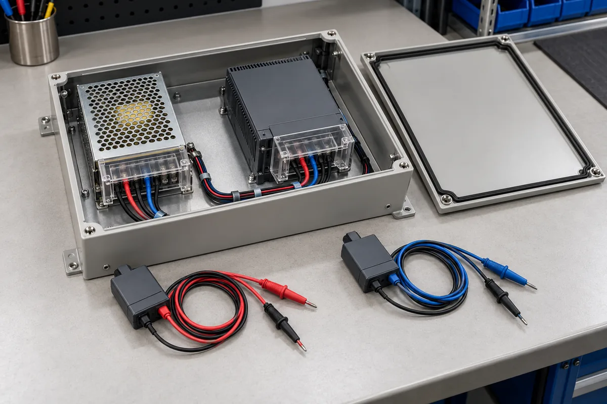
The sensing location also affects interpretation of measurements. A handheld meter at the controller and a supply display can disagree because they observe different points, even when both instruments are working correctly. Record the current at the same time as the voltage: a larger drop during a demand increase points toward the distribution path, whereas a falling source-terminal voltage can indicate a regulation boundary or another source limitation.
A shared cabinet bus makes the location of current control especially consequential. Suppose a controller and a process load share one voltage supply. Setting the source to limit their combined current does not independently regulate the process branch: the controller consumes part of the available current, and its changing demand changes what remains. If the source reaches its limit, the resulting bus voltage reduction can disturb both branches. A dedicated downstream current regulator can separate the process requirement from the controller’s voltage requirement, provided its input range and required voltage headroom are satisfied. The upstream supply then supports the combined input demand while each branch receives its intended form of regulation. This is an architectural distinction, not a reason to connect unrelated outputs together or assume a particular industrial supply supports parallel operation.
A current limit also does not establish the instantaneous current delivered during every event. Stored energy in output capacitors can flow into a connected load before the control loop reacts. Switching a sensitive device onto an already energized output can therefore differ from enabling the source with that device connected. Current-sensitive loads need documented transient behavior, suitable connection procedures, or dedicated limiting circuitry appropriate to their damage limits.
For an industrial control bus, stable voltage at the equipment is usually the service being purchased, with current limiting acting as a boundary or fault response. For a current-driven process, current accuracy and the usable voltage range define the service. This distinction gives the comparison its practical meaning: specify the regulated variable at the load, then identify what the source does when maintaining it becomes impossible.