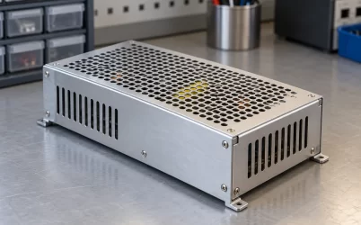
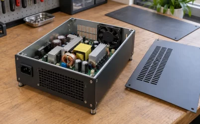
A DC-DC server power supply can connect a rack’s 48V-class distribution bus to much lower processor rails through several different arrangements. Calling that connection “direct 48V to point of load” identifies its endpoints, but does not fully describe its internal stages. Before comparing response speed, component count, or placement, locate three functions: where the voltage is regulated, where its level is transformed, and where stored energy supports a changing load.
This distinction prevents an attractive architecture label from becoming an unsupported performance claim. A single-stage conversion example and an arrangement that separates regulation from transformation can both serve a low-voltage load from a 48V input. They need not use the same control structure, external components, or transient-support mechanism. The useful comparison begins with the actual implementation rather than with a count inferred from its marketing name.
The endpoints leave the middle unresolved
A familiar intermediate-bus arrangement converts a distribution voltage to a lower bus, then uses local regulators to supply individual loads. This provides an identifiable handoff: the downstream regulator draws from the intermediate bus and controls its own output. The bus has an operating envelope, and both conversion functions have requirements at that boundary. Removing that particular intermediate voltage changes the architecture, but does not remove every internal function needed to supply the processor.
STMicroelectronics describes an isolated single-stage direct 48V-to-POL resonant solution for CPUs and DDR memories on its server and telecom application page. That is a concrete example of its stated architecture, associated with particular interface specifications. The short application description does not establish a universal response time, output-capacitance requirement, or compatibility with every processor. It should remain evidence of an available implementation approach, rather than a specification for an unnamed server board.
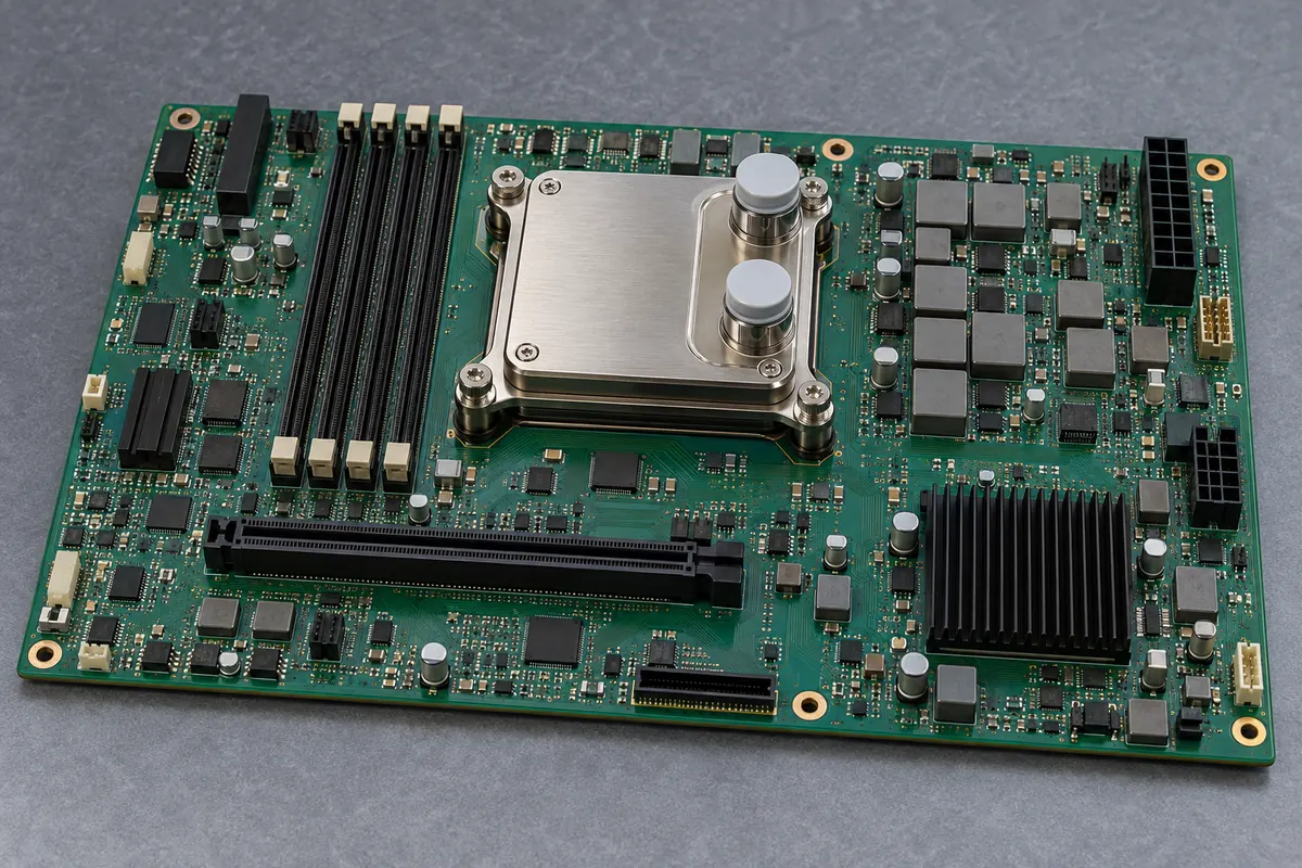
A complete compute board can place a conversion region near its load while receiving power from elsewhere in the chassis. Physical proximity can help identify the assemblies being compared. It cannot establish that the visible regulator region performs direct 48V conversion, nor reveal a control loop, an isolation boundary, or the electrical distance between its output and the processor pins.
For an architecture discussion, draw functional boxes before choosing component names. Mark the accepted input, any internal bus, each controlled output, and the load connection. Then state whether each box is a regulator, a fixed-ratio transformation function, or a combined function under the manufacturer’s definition. This makes ambiguous stage counts visible without assuming that one supplier’s terminology matches another’s.
Regulation and transformation need not occur in the same place
Voltage transformation changes voltage level. Regulation controls voltage toward a specified target despite disturbances within a supported operating envelope. A practical implementation can combine those jobs or allocate them to different blocks. The distinction becomes especially useful when an architecture describes one block near the processor and another farther away.
Vicor’s Factorized Power Architecture discussion describes a PRM regulator feeding a VTM voltage-transformation module. It contrasts that allocation with an intermediate-bus converter followed by non-isolated POL regulators. These are Vicor’s documented functional arrangements; they do not establish that every product advertised as direct conversion uses PRM and VTM functions.
This example exposes why “direct” and “single stage” should not be treated as interchangeable descriptions. A power path can deliver from 48V toward a processor without the conventional lower intermediate bus, yet still allocate regulation and transformation to separate cooperating blocks. Conversely, ST’s stated single-stage solution should be read as ST describes it, rather than reconstructed as a Vicor implementation because the endpoints resemble one another.
The practical consequence is a different question for each block. Which input variations must the regulating function accept? What relationship does the transformation function establish between its input and output? Which point determines the regulated target? How do the functions coordinate when the load changes? Without those answers, moving a box closer to the processor says little about which behavior moved with it.
It also changes the interpretation of substitutions. A replacement transformation block cannot be qualified solely by its nominal voltage ratio if the surrounding regulation arrangement depends on other behavior. A regulator with the right output voltage may still lack the required control relationship. The qualified object is the documented cooperating implementation, including the relevant interconnections and external components.
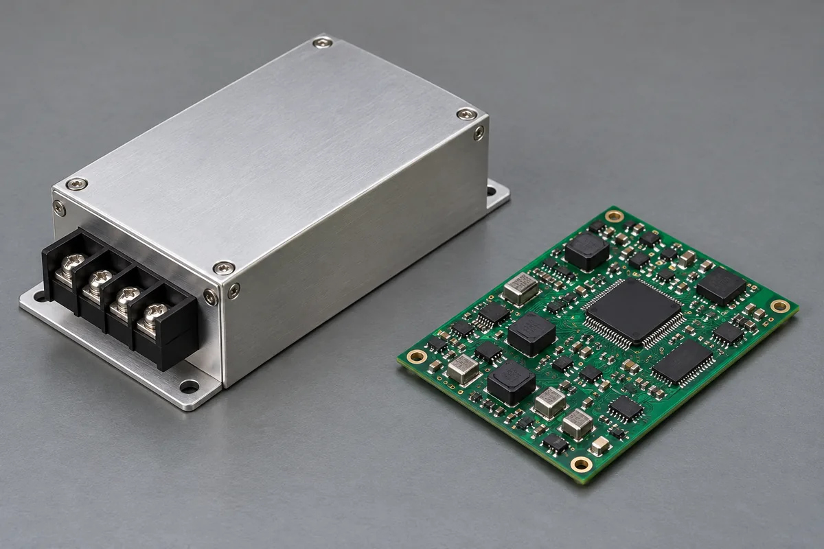
Assembly boundaries can complicate the count further. A separate converter beside a receiving board might perform a complete regulated conversion, one transformation function, or an upstream supply job. The enclosure and connector do not decide which. Integration documentation must identify the function before the physical assembly can be placed correctly in the architecture drawing.
That distinction matters during fault isolation as well as initial design. If a rail fails to meet its requirement, identify whether the target was commanded correctly, whether the transformation path received its required input, and whether distribution delivered the resulting output. These are separate questions, not a universal troubleshooting sequence. Their relevance depends on the documented architecture, and they should not be collapsed into a conclusion that the nearest visible module is defective.
A load step asks where the missing current comes from
When a processor increases demand, its supply path must provide the additional current while holding voltage within the load’s permitted behavior. Before a converter’s delivered current has adjusted, stored energy and the surrounding power-delivery network participate in the response. That statement identifies a physical requirement; it does not assign a response time or a particular capacitor bank to an unspecified architecture.
For a simplified local-capacitor interval, charge balance gives voltage change approximately equal to additional current multiplied by elapsed time and divided by capacitance. This assumes the capacitor supplies that entire current difference and ignores resistance and inductance. It helps explain the variables, but cannot predict an actual processor waveform without knowing how converter current evolves and how the network behaves.
Suppose, only as an illustration, that a capacitor supplies an extra 10 amperes for 2 microseconds. The charge removed is 20 microcoulombs. With an assumed effective capacitance of 1 millifarad, the ideal capacitive voltage change is 20 millivolts. Neither value is a proposed design limit. The example excludes connection inductance, capacitor resistance, distributed placement, and any current arriving from the converter during the interval.
The excluded details matter. A capacitance value does not state how quickly energy reaches the relevant load terminals. A capacitor on a different side of a conversion stage cannot automatically be inserted into the local equation as though it were wired across the processor. Its contribution depends on the intervening implementation. Compare the actual documented network instead of treating every microfarad in the server as one freely available reservoir.
Vicor discusses an implementation-specific relationship between energy storage and its VTM transformation function. That is a reason to examine the stated mechanism and conditions. It is not permission to apply its capacitance relationship to ST’s solution, a conventional buck regulator, or any unidentified 48V module. The endpoints alone do not establish an equivalent dynamic circuit.
Moving a boundary changes what must be demonstrated
In an intermediate-bus system, a downstream load change can disturb the local rail and alter demand on the intermediate bus. The upstream converter sees the demand presented at its own output through the intervening network. In a different architecture, those relationships must be redrawn around the functions actually present. It is unsafe to retain the old bus assumptions while deleting its box from the diagram.
A complete server chassis contains an incoming supply assembly, distribution hardware, and downstream conversion regions. Those physical regions help locate the interfaces at which claims are made. They do not prove the electrical route between them. A statement about processor-rail response and a statement about disturbance on the rack input concern different observation boundaries, even when both describe the same event.
For example, a local rail can remain acceptable during a demand change while an upstream bus experiences a measurable disturbance. Alternatively, a quiet upstream reading can coexist with an unacceptable local excursion if the local path is limiting. Neither combination contradicts conservation of energy. The network contains stored energy, conversion behavior, and impedance between the observation points.
A useful architecture comparison therefore retains more than one outcome. At the load, evaluate voltage against the receiving device’s requirements. At an upstream interface, evaluate the disturbance against the source and neighboring equipment’s permitted behavior. Where internal functions cooperate, evaluate the documented intermediate conditions too. A good result at one boundary does not automatically qualify the others.
The server power supply voltage map places the distribution bus and local rails along the facility-to-processor path. Once that role is established, the present task is to locate regulation and dynamic-support functions within the selected conversion arrangement.
Compare the implemented system, not the stage adjective
A transient comparison becomes meaningful only when the demand and acceptance conditions match. Record the initial and final load, transition rate, repetition, input condition, and observation point. Retain the actual external components and their placement. A different capacitance population or board path can change the result even when the converter names are unchanged.
The load’s required behavior also needs a definition. A processor rail following a specified load line is not necessarily supposed to maintain exactly the same voltage before and after a current change. An auxiliary fixed-voltage rail can have a different requirement. Evaluate the correct envelope rather than ranking traces by whichever appears flattest.
Thermal and mechanical conditions belong in the implemented comparison. Placing a transformation block near a processor can shorten a high-current path while introducing a local heat-removal task. A nearby processor cold plate does not establish a thermal path for the power components. Conversely, a supported shared cooling arrangement must be evaluated as documented, rather than excluded because the regulator package is separate.
Loss accounting also needs matching boundaries. A favorable figure for one block is not the efficiency of the entire conversion chain. Include the blocks and auxiliaries required to perform the same input-to-load job. Do not assign a universal efficiency benefit to deleting a named intermediate voltage; the remaining devices and their actual operating points determine the result.
Stage counting can still be useful when its definition is explicit. It can help explain integration, component responsibilities, or the interfaces needing qualification. It becomes misleading when used as a substitute for those details. Two diagrams with the same number of boxes can contain different control responsibilities, and one physical module can contain several functional regions.
A concise comparison record can therefore follow the power path in order: accepted source envelope, regulation function and observed node, transformation function, energy-storage arrangement, load interface, and demonstrated operating conditions. Identify which statements are guaranteed limits, typical demonstrations, or architectural descriptions. This preserves the distinction between a promising approach and a qualified implementation.
For a server design, the result should be a defensible assignment of responsibilities. The rack source supplies its specified interface; the selected conversion arrangement produces the required rail; the implemented network delivers acceptable behavior at the load. A direct 48V-to-POL label starts that conversation. Locating regulation, transformation, and stored energy makes it possible to finish it without assuming performance from the label.