HKS3200D1-P is a Huntkey 3,200 W class, 12 V CRPS power module. Its published maximum main-output current is 262 A at 230 Vac, 246 A at 210 Vac, and 119 A at 110 Vac. Those figures make it attractive for dense server designs, but the first purchasing question is the identity of the exact part: Huntkey titles its product page HKS3200D1-P while the specification table on that page says HKS3200D1. The suffix may matter to the ordered assembly. Before using the published table as a replacement specification, match the label, revision, host approval, and manufacturer drawing. This article explains what that identity check protects in a high-current 12 V system.
The -P suffix is a procurement boundary
The Powernexu HKS3200D1-P listing identifies the -P model and summarizes its 3,200 W rating, 12 V main output, 12 V standby output, 185 × 73.5 × 40 mm dimensions, and 262 A maximum at 230 Vac. Huntkey’s manufacturer page headed HKS3200D1-P provides three input-specific current rows. Yet the model cell in its own specification table drops the -P suffix. This is an editorial inconsistency in public documentation, not proof that the two suffix variants are electrically or mechanically identical.
It is tempting to treat the suffix as a minor catalog convention because the voltage, power class, and metal enclosure look familiar. A service spare has to be more precise. The orderable part number can encode a connector, firmware build, efficiency or regional configuration, or a vendor-specific revision, even when a short public table does not explain the code. None of those differences should be inferred for this particular suffix; the point is that the available page does not rule them out. Ask the supplier for a photograph of the actual nameplate, an exact manufacturer part number, and a revision-controlled drawing that explicitly names the -P unit. Compare those records with the server maker’s approved spare list.
Read the 12 V figures at their stated inputs
Huntkey’s public table lists a 90–264 Vac, 47–63 Hz input range and support for 240 Vdc. The output rows are more specific. At 110 Vac the main 12 V rail has a published maximum of 119 A; at 210 Vac it is 246 A; at 230 Vac it is 262 A. Each row lists a 3 A minimum load, ±5% voltage regulation, and no more than 120 mVp-p ripple and noise. The table does not state the test setup for those ripple figures, so they should not be turned into a system-level noise guarantee at an accelerator card.
| Published input condition | Main-output current ceiling | Nominal 12 V arithmetic |
|---|---|---|
| 110 Vac | 119 A | 1,428 W |
| 210 Vac | 246 A | 2,952 W |
| 230 Vac | 262 A | 3,144 W |
The last column is 12 V multiplied by current; it is not a second manufacturer rating. In particular, 262 A times nominal 12 V yields 3,144 W rather than precisely 3,200 W. A nameplate power class, output-voltage tolerance, standby output, and rating convention need not produce a neat multiplication. Do not resolve the 56 W gap by inventing a hidden rail or assuming an undocumented short-duration overload capability. Use the manufacturer-approved combined-output definition when building a final power budget.
The 90 Vac lower input boundary is not a promise of 3,200 W across the full input range. The available table contains only three AC output rows. It does not publish a continuous derating curve, a threshold between 110 and 210 Vac, or a separate 240 Vdc current ceiling. If a site uses DC distribution or a feed that can sag into an unlisted band, obtain the proper operating table. Interpolation between these points may seem convenient, but a control limit could change discretely. The rack feed at the PSU inlet, including transfer and low-voltage conditions, determines which current entry is relevant.
Follow 262 A through the connector and board
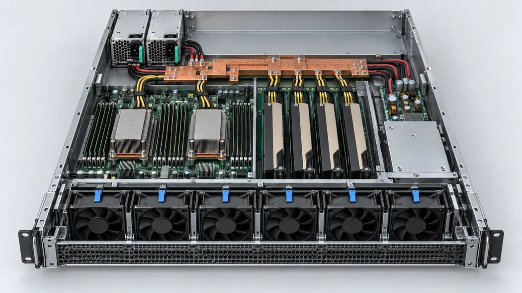
A high-current 12 V supply is useful only if the path from its output contacts to the loads can carry the applicable current. The module’s connector mates with a power distribution board or backplane. From there, copper planes or busbars, protection devices, harnesses, and local converters feed processors, accelerators, memory, drives, fans, and management circuits. The supply’s current limit describes one boundary of that path. It does not grant a 262 A rating to every contact or board trace downstream.
For a simple hypothetical example, imagine a server with 115 A of 12 V input allocated to accelerator converters, 70 A to processor and memory converters, 38 A to drives and fans, and 20 A to other branches. The sum is 243 A before any additional margin or transient behavior. At the published 230 Vac point, that total is below 262 A, while at 210 Vac it approaches the 246 A entry. It is far above the 119 A entry at 110 Vac. Those branch numbers are an illustration of budgeting, not a measurement of HKS3200D1-P or a recommendation for a real server.
Even a total below 262 A can conceal a hot connection. A mating pair with extra resistance from wear, poor seating, or contamination dissipates heat where the current crosses it. Multiple output contacts may share the total current, but their individual ratings and actual division depend on the connector design. The public product page does not provide a pin assignment or per-contact limit. A drawing for the ordered part and a temperature-rise assessment for the host assembly are needed. Voltage measured at the PSU can also differ from voltage at a remote converter after busbar and contact drops.
The 12 V standby rail has a different job. Huntkey lists 0.1–2.1 A on +12 VSB, with ±5% regulation and the same listed ripple limit. It supports a host’s standby and management scheme only if the interface and sequencing match. It should not be counted as another 2.1 A available to the main compute bus. A bench load can show stable main output while a real server still rejects the module because standby timing, presence detection, or controller communication differs from what the host expects.
Separate physical fit from an approved spare
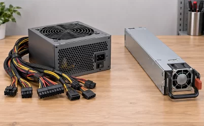
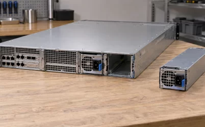
The published enclosure size is 185 mm long, 73.5 mm wide, and 40 mm high. That is enough to screen a bay for gross clearance, but not to establish interchangeability. The latch can meet the chassis at a different point. The output connector can have another key or contact arrangement. Even if the hardware slides in, the host controller may require a specific identification response or firmware revision. A replacement must match both the electrical mating system and the server maker’s supported configuration.
Huntkey advertises N+1 redundancy, cold standby, hot swapping, black-box fault recording, and online firmware upgrade functions. Those are useful product capabilities, but the public page does not give the management command map, firmware compatibility matrix, fault-log schema, or a supported chassis list. Do not take the presence of those feature names as proof that a particular backplane will share current correctly or permit a live swap. Verify the approved host assembly and service procedure. For a new platform, obtain integration documentation before treating these functions as available to the BMC.
For an existing server, the strongest evidence is an approved spare part entry that names the exact assembly and revision. If it is unavailable, the integrator needs the mechanical drawing, connector specification, management-interface requirements, and controlled integration testing. The public 185 × 73.5 × 40 mm envelope is a starting point, not a substitute for those records. The manufacturer-page suffix discrepancy should be included in the query to the supplier so the answer identifies whether the table applies to the -P part being quoted.
Redundant operation exposes the weakest feed
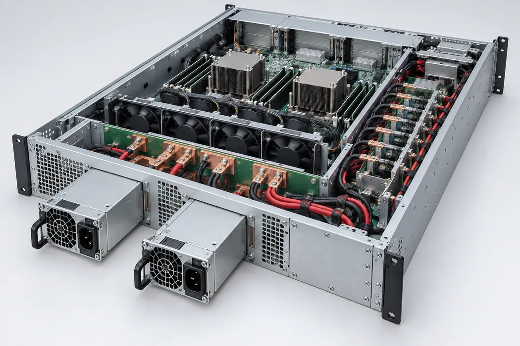
In a two-module 1+1 configuration, each unit may carry part of the load during normal operation. The protected load is the amount the survivor can carry after one module or its feed disappears, assuming the host supports that transfer. If a hypothetical server draws 200 A on the common 12 V bus, a pair at 230 Vac may have sufficient published single-module current for the settled load. If the surviving module is on a 110 Vac feed, its listed 119 A ceiling does not support the same 200 A steady load. Normal sharing can hide that shortfall until the fault that redundancy is intended to cover.
Huntkey’s N+1 statement includes 0≤N≤3, but it is not a wiring diagram for every shelf. The controller, backplane, and current-sharing method define permitted population and fault handling. A high-power shelf may have more than two bays, yet its protected capacity cannot be obtained by simply multiplying 262 A by the number of installed modules. The allowed total also depends on board current, input feeds, cooling, and the number of units that must remain after a fault. Model those failure states against the particular host, not the brochure phrase.
Use efficiency and temperature as operating conditions
Huntkey calls the product 80 PLUS Titanium and lists efficiency minima of 90% at 10% load, 96% at 20%, 96% at 50%, and 93.5% at full load. Its headline says efficiency exceeds 96% in the 20%–50% load range. These are manufacturer statements associated with defined conditions, not a constant efficiency to apply at every site voltage, temperature, or load. If a procurement policy requires certification for the exact -P revision, request the current certificate or test record that identifies the ordered model rather than relying solely on a catalog tier.
Loss inside a compact supply becomes heat that its forced-air system must remove. Huntkey lists an operating air temperature of 0–55°C and forced-air cooling, but the public summary does not map every output-current row to every inlet temperature. Nor does it state the server bay’s required pressure, fan response, or permitted airflow obstruction. A dense chassis may preheat the air reaching the PSU; conversely, a removed module can change the bay airflow. Check the temperature at the actual supply inlet and the host’s flow direction before assuming the 230 Vac current entry is continuously available in a crowded rack.
Huntkey lists input undervoltage, input overvoltage and current limiting, output overvoltage, overcurrent and short-circuit protection, and overtemperature protection. These names do not reveal trip points, delays, or recovery behavior. They cannot be used to size branch fuses or to predict whether a load step will shut down the module. Obtain the revision-specific protection data when coordination matters. The public listing likewise mentions 240 Vdc support without a DC current row or installation instructions; DC input planning needs those details before substituting a DC source for an AC feed.
What a replacement order must establish
A defensible order for HKS3200D1-P identifies the suffix on the physical label, confirms which Huntkey table applies to that suffix, and names the host-approved assembly or supplies the integration drawing. It states the lowest input voltage expected at each PSU bay in normal and failure operation. The load record uses 12 V amperes, with steady and short-duration demands distinguished, and it identifies the PDB and connector ratings rather than assuming the PSU nameplate covers them.
If the host is already qualified, use its approved spare and service instructions as the replacement authority. If it is a new design, resolve the exact connector, management, standby, airflow, and current-sharing interfaces with the vendor before qualification. Keep the 119 A, 246 A, and 262 A entries attached to their respective AC inputs. Until Huntkey confirms why the -P heading and non-P model cell coexist, retain that documentation issue in the purchase record. It is a small text discrepancy with potentially large consequences for a 12 V, 262 A server power path.