An open-frame power supply does not acquire a reliable ground connection simply because its circuit board is screwed to a metal enclosure. The correct connection depends on what each marked terminal or mounting hole does, whether the final equipment uses protective earthing, and how the converter controls electrical noise. On one board a plated fixing hole may be an intentional functional-ground point; on another, a similar-looking hole may be only mechanical. Nor is the negative DC output automatically the same node as chassis or protective earth. Grounding an open-frame supply means tracing these different paths through the actual board and host enclosure, not adding a green wire to the nearest screw.
The distinction matters during enclosure design. A mechanically sound installation can still interrupt a required high-frequency return path with a painted standoff. A quiet-looking DC output can be referenced to the chassis in a way that creates an unwanted loop. Most seriously, a functional connection intended to reduce electromagnetic interference should not be mistaken for the protective path needed to handle a fault. The supplier’s installation drawing and the end product’s electrical architecture decide which connections are required.
A mounting hole is an electrical connection only when the board makes it one
Open-frame converters commonly use several holes to support the PCB on standoffs. Their identical diameters do not imply identical electrical roles. A hole might be isolated from all copper, connected to an EMI-filter node, tied to chassis or frame ground, or used as a designated protective-earth connection. Copper plating around one hole is a clue, not permission to infer its function from appearance alone. The board artwork can be revised, and a washer can contact a different region from the one visible above the PCB.
The relevant drawing should identify electrical and mechanical mounting points separately. Read the manufacturer’s definition of FG, PE, chassis, and any ground symbol in that document. Those abbreviations are not interchangeable across suppliers. In some designs an FG marking describes a functional connection that helps a noise filter; in others the installation instructions also specify a protective-earth termination. If a drawing specifies a particular fixing hole, a different unused hole on the same board is not an equivalent substitute merely because the screws fit.
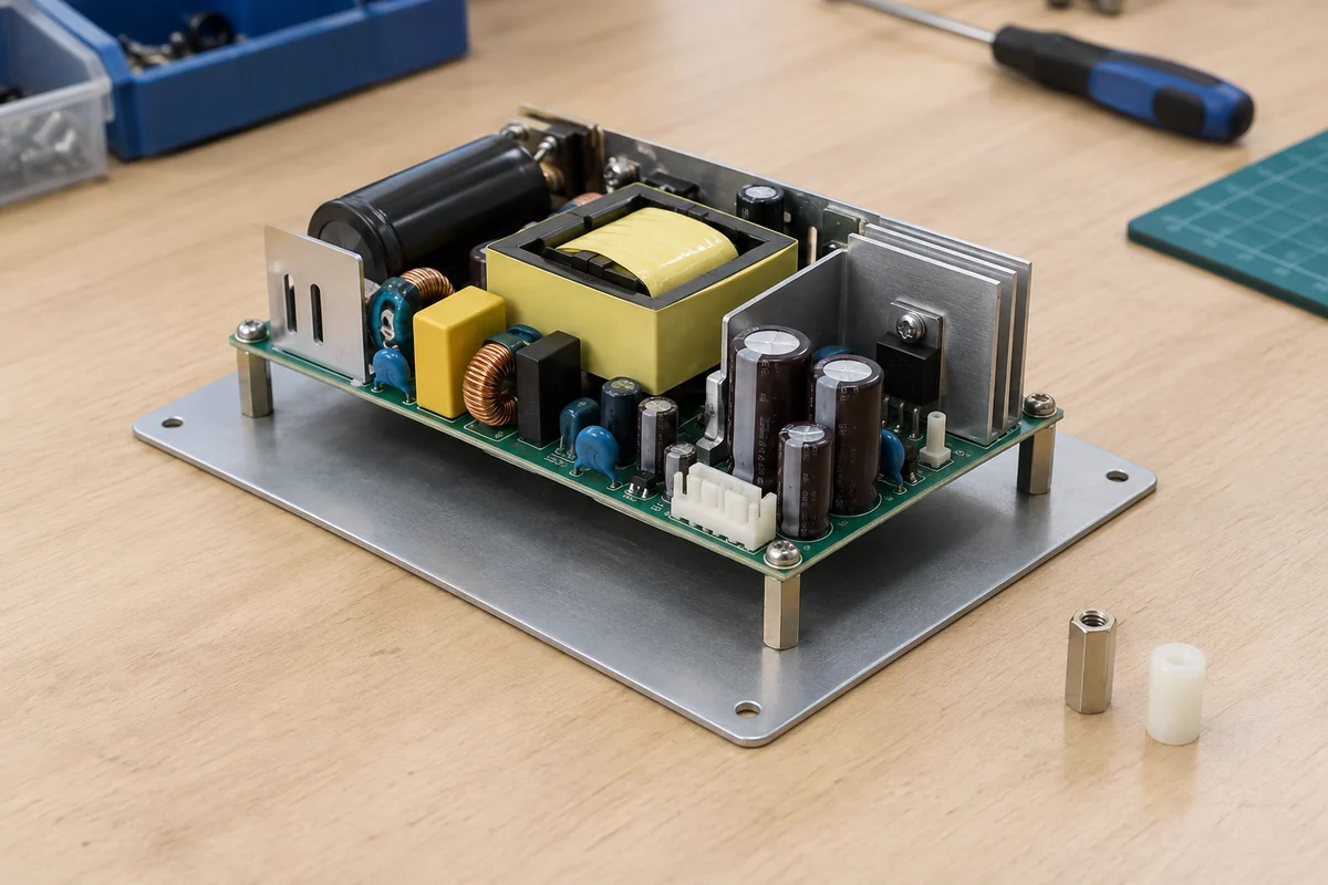
A useful illustration comes from TDK-Lambda’s explanation of grounding its ZPSA open-frame supply. In that identified design, capacitor traces reach particular plated mounting holes. The manufacturer shows two different capacitor connections and notes that there is no PCB trace between those two holes. The grounded metal mounting plate and conductive standoffs complete the intended high-frequency path. That is a model-specific example of why the installation drawing matters, not a claim that every open-frame board uses the same pair of holes or the same mechanical arrangement.
Protective earth and DC return have different jobs
In equipment whose safety architecture calls for a protective-earth connection, the protective path bonds relevant accessible conductive parts and provides a route for fault current. Its continuity must survive ordinary assembly tolerances and foreseeable service conditions. A converter’s low-voltage negative output, by contrast, is the circuit return for its load. It may be isolated from protective earth, connected at an intentional point, or otherwise referenced according to the particular system. The words “ground” and “0 V” do not settle that choice.
Suppose a controller enclosure has a metal chassis and an open-frame AC-DC supply with an isolated output. The chassis may require a dependable protective bond even if the output return floats. Connecting the output return to chassis at several convenient screws could create parallel return paths through signal shields, cabinet panels, and communications cables. That can inject switching noise into sensitive circuits or complicate fault finding. Conversely, a deliberately specified output reference may be important to the equipment’s noise and immunity behavior. Neither arrangement can be selected safely from a generic picture of an open-frame PCB.
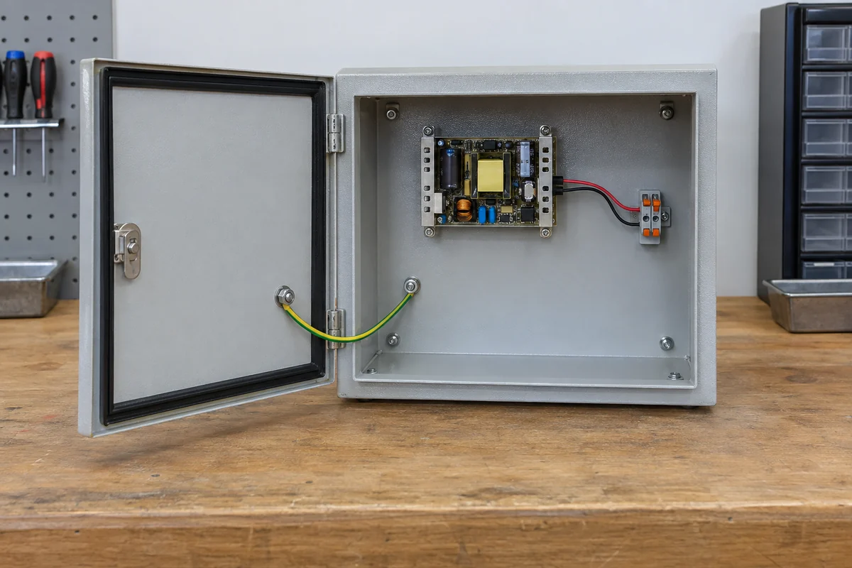
The AC input protective-earth conductor, when one is required, must not be routed through an ordinary signal connector, a removable control board, or a casual length of exposed PCB copper because it happens to reach the same metalwork. The physical termination, conductor, fastener, and host bond are part of the safety design. A vendor-provided earth point on the PSU can also have a different role from the enclosure’s main protective bond. Some manufacturers explicitly tell integrators to bond the host chassis separately rather than assume the PSU earth terminal alone carries the end product’s protective obligation.
Why a functional bond can change conducted noise
Switching supplies produce high-frequency common-mode as well as differential-mode noise. Capacitors and filter structures may give some of that current a controlled return path to chassis or another designated reference. If the intended connection is absent, the current does not disappear. It can seek a less predictable route through the output harness, signal wiring, shield braid, or external ports. A cable that looked electrically insignificant at DC can become an effective high-frequency path and a source of emissions trouble.
TDK-Lambda’s ZPSA example is unusually instructive because it shows how input-side and output-side filter capacitors reach different mounting holes. An integrator who grounds only the metal box while leaving the specified PCB contact isolated has not reproduced the manufacturer’s demonstrated arrangement. Equally, joining unrelated nodes just to make an ohmmeter read zero could bypass the intended separation. The correct high-frequency return has to come from the actual board documentation, its filter layout, and the assembled enclosure.
Frequency matters here. A long wire may show excellent DC continuity yet present enough impedance at switching frequencies to perform differently from a short, broad chassis contact. Contact area, the route through a standoff, and proximity to the AC input or output cable can influence the noise path. None of that means a protective-earth conductor should be shortened or relocated without regard to its safety function. The safety and EMC roles must both be met, sometimes by related but not identical physical connections.
Nor is “bond everything together” a universal cure. Unplanned extra contacts can create loops or shift noise onto an interface that had previously been quiet. A plastic standoff in one position and a metal one in another may be exactly what a manufacturer intended. The installation instructions, not a preference for all-metal or all-insulating hardware, determine the relevant arrangement.
Paint, standoffs, and spacing alter the finished path
At the mechanical interface, the details are easy to overlook. Paint or anodizing can interrupt a contact that a bare-metal prototype provided. An insulating shoulder washer can isolate the screw even when its shaft is metal. A toothed washer might pierce coating in one production unit but contact only its surface in another if torque and stack-up vary. A removable panel can carry a bond in the laboratory and then lose it after a service operation. These are not merely cosmetic details when a designated board contact depends on the metal mounting surface.
The opposite failure is a short where isolation was intended. An overwide washer, an incorrectly sized standoff, or a shifted mounting bracket can approach a primary-side pad or exposed component lead. Open-frame boards also have an underside: a metal tray beneath it can reduce the clearance available from solder joints and traces. COSEL’s open-frame handling guidance specifically cautions that required insulation distance must be preserved between component leads and a metal chassis and describes insulating material as a possible remedy when the required distance cannot otherwise be obtained. The needed distance and acceptable material belong to the selected product and final-equipment design; there is no single dimension to apply to every board.
This creates a useful design tension. Making a designated FG fixing point conductive may be essential to a noise-control arrangement, while nearby regions still need electrical separation from the same chassis plate. The correct mounting assembly therefore cannot be summarized as “use metal standoffs” or “use plastic standoffs.” It may need different hardware at different locations. Screw length, washer diameter, board flex, manufacturing tolerance, and movement under vibration all affect whether the installed unit preserves the intended boundary.
Class I and Class II equipment do not share one grounding recipe
Terms such as Class I and Class II describe different protection approaches for the complete equipment and its applicable evaluation, not a simple choice of wire color. In a Class I design, accessible conductive parts normally rely on protective earthing as part of protection against electric shock. A Class II design relies on a different insulation strategy and may have no protective-earth connection at the mains inlet. The selected power-supply variant, its approved conditions, and the host construction have to support the approach; an installer cannot convert one approved arrangement into the other by omitting an earth wire.
Functional grounding can still be a question in a design without a protective-earth conductor. A supplier may specify a connection for noise control, or may provide a different filter configuration for that use. But a functional reference is not a substitute for the insulation, spacing, and accessibility conditions needed by a Class II end product. Connecting it to an accessible metal panel without understanding those conditions would change the equipment architecture, not merely improve EMI.
There is also no blanket rule that an isolated DC output must be left floating. The end equipment may intentionally reference one side for sensing, shielding, or communications, subject to its safety and EMC design. What is unsafe editorially and technically is to prescribe a universal output-to-PE link. An output symbol on a wiring diagram, an FG mark beside a screw, and a protective-earth symbol at the AC inlet can represent three different connections. The exact supplier drawing resolves their relationship.
When a noise symptom points toward the mounting interface
A grounding problem may first appear as excessive conducted emissions, unstable sensor readings, or a change in noise when an enclosure panel is fitted. Such symptoms do not prove the PCB is defective. Consider an otherwise unchanged open-frame converter whose assembly was moved from a bare-metal prototype plate to a painted production tray. If its specified filter-contact hole now lands on paint, the high-frequency return path may differ while the supply still delivers normal DC voltage. A technician who only measures output voltage could miss the installation change.
That distinction also limits the remedy. Adding a random bond strap might lower one measured emission while making another port noisier or upsetting the intended safety separation. In contrast, restoring the exact mounting contact specified for a known board can return the assembly to the condition its manufacturer characterized. Any change still belongs within the equipment’s approved engineering process; a successful bench symptom test alone is not evidence of full EMC or safety compliance.
Two boards can require opposite-looking mounting choices
Picture two open-frame supplies with similar outlines in otherwise similar metal enclosures. The first manufacturer’s drawing identifies a plated mounting hole as the return for an input-filter capacitor network and requires a conductive contact to the grounded mounting plate. The second uses that location only for mechanical support and specifies insulation from nearby copper. A metal standoff that helps the first installation could defeat the second board’s intended spacing. The generic label “open frame” does not tell the integrator which case applies.
For the actual project, resolve the map at the interface: marked board point, mounting hardware, enclosure contact, protective conductor where required, output reference, and any specified filter connection. That map is more useful than a universal rule about connecting every ground symbol together. When it is drawn for the selected PSU and the final host, the apparently small choice between a plated hole, an insulating standoff, and a chassis bond becomes an understandable part of the equipment design rather than a guess hidden beneath the board.