An industrial grade power supply is not defined by one voltage, form factor, topology, or universal certification. For sourcing purposes, the term is useful only when the exact model can support the machine’s input source, load behavior, installation, cooling, environment, compliance boundary, and service plan. Buyers should therefore compare documented operating conditions and supplier evidence rather than treating “industrial grade” as a specification by itself.
The practical task is to identify the right conversion path—AC-DC or DC-DC—select an installation format such as DIN-rail, enclosed, open-frame, or rack-mounted, and then reject candidates whose ratings depend on unresolved thermal, transient, protection, approval, or lifecycle assumptions.
Quick answer: what makes a power supply suitable for industrial use?
A suitable industrial power supply converts the available source into the required DC output while supporting every relevant machine state, including startup, normal production, peak loading, shutdown, and credible faults. Its documented rating must apply at the actual input voltage, ambient temperature, altitude, orientation, and cooling condition. The supplier should also provide enough evidence to establish mechanical fit, protection behavior, safety and EMC scope, production consistency, and lifecycle control. “Industrial grade” can describe the intended market, but the exact model documentation establishes whether the supply is suitable for a particular installation.
The label is a hypothesis, not the shortlist
Industrial equipment ranges from clean, temperature-controlled control cabinets to outdoor machinery, process systems, factory automation, telecom infrastructure, transportation equipment, and production tools exposed to contamination or vibration. These environments do not impose one common electrical or mechanical requirement.
Current manufacturer catalogs reflect that breadth. For example, XP Power’s industrial power supply application overview presents the category through application requirements rather than one universal architecture. A model marketed for industrial use might be an enclosed AC-DC unit, an exposed board for installation inside another product, a DIN-rail module, or a DC-DC converter supplied from an existing bus.
The label alone does not establish:
- the permitted input range or behavior during source disturbances;
- continuous output at the deployed temperature and cooling condition;
- support for motor, solenoid, capacitive, or pulsed load startup;
- resistance to dust, moisture, chemicals, vibration, or shock;
- the scope of safety approvals or EMC test evidence;
- expected operating life in the actual thermal environment;
- availability of controlled replacements over the machine’s service life.
A meaningful shortlist replaces the adjective with model-specific statements. Instead of requesting a “rugged 24 V industrial PSU,” the requirement should identify the source, load states, installation format, thermal conditions, environmental exposure, required evidence, and replacement policy.
Choose the power path before comparing catalog models
The first architectural question is where conversion should occur. If facility AC enters the machine, an AC-DC supply can create the main control or actuator bus. If the equipment already has a stable DC bus, a DC-DC converter may generate an isolated or regulated point-of-load rail. Some systems use both: a central AC-DC stage establishes a machine bus, followed by distributed DC-DC conversion near sensitive or distant loads.
| Machine condition | Architecture worth evaluating | Potential advantage | Question that remains open |
|---|---|---|---|
| Facility AC feeds a control cabinet | Enclosed or DIN-rail AC-DC supply | Direct creation of the machine DC bus | Does the documented output apply at the cabinet temperature and input source? |
| A regulated DC bus already exists | DC-DC converter | Local regulation, voltage conversion, or isolation where specified | Can it tolerate the bus range, disturbances, grounding scheme, and load dynamics? |
| The PSU is built inside protected equipment | Open-frame AC-DC or DC-DC assembly | Flexible integration and potentially efficient use of enclosure space | Who provides guarding, airflow, earth bonding, insulation, and final-equipment compliance? |
| High-power equipment needs module-level service | Enclosed, rack-mounted, or modular power assembly | Defined replacement and distribution arrangement | Are current sharing, isolation, control, and live replacement actually supported? |
| Loads are distributed over long cable routes | Central DC bus with local conversion, where appropriate | May reduce voltage-drop sensitivity at low-voltage loads | How are grounding, protection coordination, conducted noise, and fault isolation handled? |
Centralized conversion simplifies the number of active power stages, but it can create long high-current runs and concentrated failure exposure. Distributed conversion can place regulation near the load, although it introduces more converters, interfaces, grounding decisions, and potential noise paths. Neither arrangement is inherently more industrial; suitability follows from the machine architecture and service model.
Regenerative loads deserve separate treatment. Drives, motors, coils, and electromechanical actuators may return energy to the DC bus during deceleration or switching. Many power supplies are designed to source current, not absorb sustained returned energy. If reverse energy is credible, the system may need braking, clamping, storage, or another documented management method rather than assuming the PSU will sink it.
Form factor assigns engineering responsibilities
DIN-rail, enclosed, open-frame, and rack-mounted describe installation formats, not interchangeable quality levels. Each format determines how much of the final power system is supplied by the PSU manufacturer and how much remains with the equipment integrator.
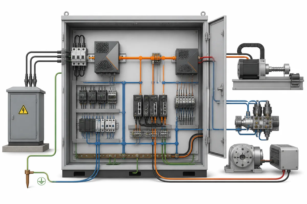
DIN-rail modules
DIN-rail supplies are well suited to control panels where standardized rail mounting, organized wiring ducts, terminal access, and field replacement are priorities. Their cabinet position still affects temperature, convection, conductor routing, clearance, and accessibility. Mounting several heat-producing devices tightly together can create a local environment substantially hotter than the room containing the cabinet.
Enclosed supplies
An enclosed power supply adds a metal or polymer housing around the conversion assembly and may provide terminals, connectors, or an integral fan. The housing improves mechanical protection compared with an exposed board, but it does not automatically establish a dust, water, or chemical ingress rating. The exact enclosure documentation and installation instructions define that boundary.
Open-frame supplies
An open-frame unit transfers substantial responsibility to the host equipment. The finished machine must provide protection from contact, secure mounting, grounding where required, airflow, wiring segregation, and an appropriate fire and mechanical enclosure. A detailed 24 V open-frame power supply design discussion shows how the exposed board, DC distribution, and host enclosure operate as one system.
Open-frame construction can be appropriate when the power stage is deeply integrated into a controlled enclosure. It is a poor substitution for an enclosed module when operators or maintenance personnel could access hazardous parts or when the host cannot reproduce the cooling and spacing assumed by the PSU documentation.
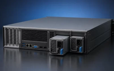
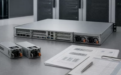
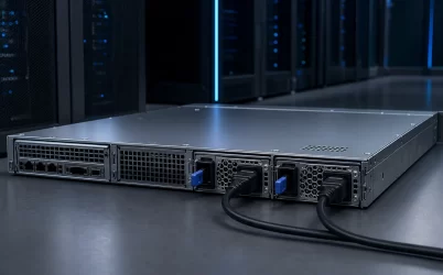
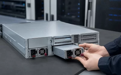
Rack-mounted and modular assemblies
Rack-mounted or removable modules can support higher centralized power and service-oriented equipment. A removable handle does not by itself prove hot-swap operation. Live replacement requires a compatible backplane or distribution assembly, controlled insertion behavior, fault isolation, supported current transfer, and a system architecture capable of carrying the load while a module is absent.
Build ratings from machine states rather than one load total
A machine rarely presents one constant demand. Controls may power first, capacitive inputs may charge, contactors may close, valves and solenoids may energize, motors may accelerate, heaters may cycle, and communications equipment may reboot after an interruption. A supply that supports the average production load can still fail during the sequence that brings the machine into production.
Separate the load into operating states:
- Standby: control electronics, monitoring, safety circuits, and communications remain active.
- Startup: downstream capacitance charges and multiple loads may energize within a short interval.
- Normal operation: the equipment carries its sustained production demand under expected duty cycles.
- Peak operation: actuators, motors, heaters, transmitters, or computing loads overlap temporarily.
- Fault and recovery: protection operates, a branch is disconnected, or the system attempts an automatic restart.
- Shutdown or deceleration: stored mechanical or magnetic energy may return to the bus.
For each state, determine the required voltage at the load, not just at the PSU terminals. Cable resistance, connectors, fuses, relays, and distribution boards can create enough drop to disturb devices at the far end of a low-voltage bus. Remote sensing may compensate for some distribution drop when the exact supply supports it, but incorrect sensing or an open sense connection can create a different failure mode. The supplier’s connection instructions matter.
Output ratings also need conditions. A nameplate power value may apply only over part of the input range or with specified forced air. Available output can decline at high temperature, high altitude, low input voltage, or an unfavorable mounting orientation. Compare candidates using their deployed rating after applicable derating, not the largest number on the product page.
Protection behavior must fit the load. Overcurrent protection may use current limiting, foldback, hiccup restart, or latching shutdown, depending on the model. A high-capacitance load or motor controller that appears as a temporary overload could repeatedly trigger hiccup protection and never start. Conversely, an oversized supply with a high fault-current capability may require careful branch protection so wiring and downstream devices are protected before excessive energy reaches them.
Environmental claims need coordinates
“Harsh environment” has little procurement value until the stress is named and quantified by the project. Temperature, altitude, humidity, condensation, conductive contamination, corrosive atmosphere, dust, vibration, shock, and cooling-air quality affect different parts of the design.
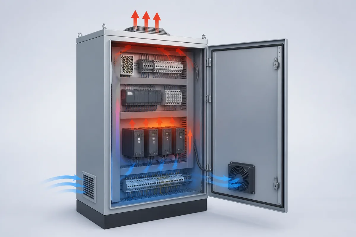
Ambient temperature is especially easy to misstate. The relevant temperature may be the air entering the PSU, the local air inside a cabinet, or a temperature measured at a defined component or case location. A room-temperature requirement does not describe a sealed cabinet warmed by drives, controllers, and adjacent supplies. Supplier thermal curves and measurement definitions are therefore more useful than a single maximum-temperature headline.
Cooling evidence should identify whether the rating assumes natural convection, a specified airflow, an integral fan, conduction into a mounting surface, or some combination. For fan-cooled units, service planning should address fan wear, contamination, alarm behavior if provided, and replacement access. For convection-cooled products, installation spacing and orientation can determine whether the expected airflow path exists.
Conformal coating can mitigate certain contamination and humidity risks, but it does not turn an open board into a sealed enclosure. Similarly, a metal cover does not establish resistance to water, conductive dust, salt mist, or aggressive chemicals. Those claims require model-specific construction and evidence applicable to the deployed condition.
Approval marks do not transfer automatically to the machine
A power supply may carry safety approvals or be evaluated as a recognized component under defined conditions. That evidence can reduce final-equipment work, but it does not automatically approve the completed machine. Installation details such as earthing, fuse selection, wire ratings, spacing, accessibility, enclosure construction, operating altitude, and maximum ambient can remain conditions of use.
EMC behavior is similarly system dependent. A laboratory result for a PSU reflects a particular input filter, load, grounding arrangement, cable configuration, enclosure, and test setup. Long actuator cables, variable-speed drives, contactors, and shared grounding paths can change conducted and radiated behavior after installation.
Useful supplier evidence identifies what was tested and what external components or installation practices were required. If the report assumes an additional filter, shield termination, ferrite, minimum load, or particular chassis connection, that condition belongs in the machine design and bill of materials. A bare statement that a model is “EMC compliant” does not reveal those dependencies.
Turn the quotation into an evidence package
Commercial comparison becomes more reliable when every important requirement is paired with the document or test result expected from the supplier. This prevents two candidates with similar voltage and wattage labels from appearing equivalent when one has unresolved operating conditions.
| Requirement area | Evidence to request | Reason to hold or reject a candidate |
|---|---|---|
| Input source | Input range, frequency or DC-bus limits, inrush information, source-disturbance behavior, and applicable derating | The deployed source falls outside a documented condition or upstream protection cannot support startup |
| Output and dynamic loads | Voltage tolerance, ripple conditions, transient or peak-load data, startup behavior, and remote-sense instructions where applicable | Motor, capacitive, pulsed, or overlapping loads are supported only by an unsupported assumption |
| Thermal operation | Derating curves, airflow definition, orientation limits, temperature measurement point, and fan information | The quoted rating depends on cooling the machine cannot provide |
| Protection behavior | Descriptions of overvoltage, overcurrent, overtemperature, and short-circuit response, including recovery mode | Protection can trap the real load in restart cycles or does not coordinate with branch protection |
| Mechanical integration | Controlled drawing, mounting instructions, terminal or connector details, clearances, and service-access requirements | The product fits nominally but blocks wiring, airflow, extraction, or safe access |
| Safety and EMC | Current certificates or listings, report scope where available, conditions of use, and EMC test configuration | The required market, equipment category, or installation condition is outside the documented scope |
| Environment | Evidence addressing the project’s actual temperature, altitude, vibration, shock, humidity, or contamination requirement | “Industrial” or “rugged” substitutes for a defined test condition |
| Production and lifecycle | Revision identification, change-notification process, traceability, availability policy, and approved replacement approach | The supplier cannot control changes that could invalidate machine qualification or field replacement |
Reliability figures also need context. A calculated mean-time-between-failures value depends on a prediction method and assumptions; it is not a promise that each unit will operate for that duration. Component life can be strongly influenced by internal temperature, load, ripple current, switching cycles, contamination, and fan condition. For long-service industrial equipment, thermal design and replaceability may be more actionable than one isolated reliability number.
Customization should remain inside the same evidence discipline. A changed connector, cable length, coating, fan, mounting plate, control signal, or output setting can create a useful machine-specific variant, but it may also alter thermal behavior, EMC performance, safety scope, or production identity. The quotation should state which changes are controlled, which documents will be revised, and whether the modified version remains covered by the cited approvals and test evidence.
Shortlist by unresolved risk, not feature count
A practical sourcing process can reduce a long catalog list in three passes. First, remove architectures that do not fit the source, distribution plan, enclosure, mounting, or service method. Second, remove models that cannot support startup, peak demand, regenerative behavior, fault recovery, or continuous output under the deployed input and thermal conditions. Third, compare the remaining suppliers by the completeness and control of their evidence, including drawings, curves, approval scope, change notification, traceability, customization boundaries, and replacement planning.
This method may leave two supplies with the same nominal voltage and power on opposite sides of the shortlist. One may have a lower headline rating but complete thermal and transient evidence for the machine. Another may advertise more power while depending on unspecified airflow, an unsuitable protection mode, or approval conditions that do not cover the installation.
An industrial grade power supply becomes a defensible purchase when its place in the machine architecture is explicit and its important claims remain true under documented operating conditions. Architecture determines what the supply must do; supplier evidence determines whether the selected model has demonstrated that it can do it. Everything still unresolved—cooling, startup, reverse energy, environmental exposure, compliance scope, or lifecycle control—remains a project risk rather than an industrial-grade capability.