A linear power stage can become attractive when its input is close to the required output: less voltage is discarded while supplying the load. Bring the input too close, however, and the selected regulator may lose regulation. Raise the input to restore headroom and its dissipation increases. This conflict gives linear versus switching power supplies for industrial applications a useful engineering boundary: can the proposed arrangement satisfy low-input regulation and high-input thermal requirements at the same time?
The answer belongs to a defined conversion stage. A complete mains-powered linear supply and a local linear regulator after an industrial switching supply are different objects. Comparing them without identifying their boundaries can turn valid regulator arithmetic into an invalid claim about an entire cabinet’s energy use, isolation, or suitability.
Separate the purchased supply from the local rail
Begin with the actual power path. Does the project compare complete AC-input supplies feeding the same equipment? Or does it already have a DC bus and need another regulated rail near a controller? The second question concerns local conversion. A linear stage in that position can coexist with a switching front end, so the final equipment need not belong exclusively to one category.
For a complete AC-input comparison, retain each candidate’s documented input, output, load behavior, protection, isolation, thermal conditions, and applicable approvals. The results of a DC regulator calculation do not establish the losses or safety properties of all its upstream conversion hardware. A local stage also does not replace the mains input protection, enclosure, or protective arrangement of the finished equipment.
Analog Devices’ AN-140, Basic Concepts of Linear Regulator and Switching Mode Power Supplies, by Henry Zhang, explicitly addresses non-isolated applications. It explains the linear stage’s voltage-drop loss and minimum headroom for regulation. Those concepts support the local-rail analysis here. Its illustrative circuits do not specify a complete industrial mains supply or authorize a particular regulator for an unidentified machine.
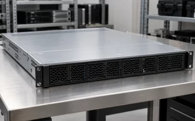
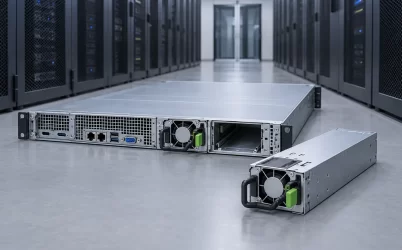
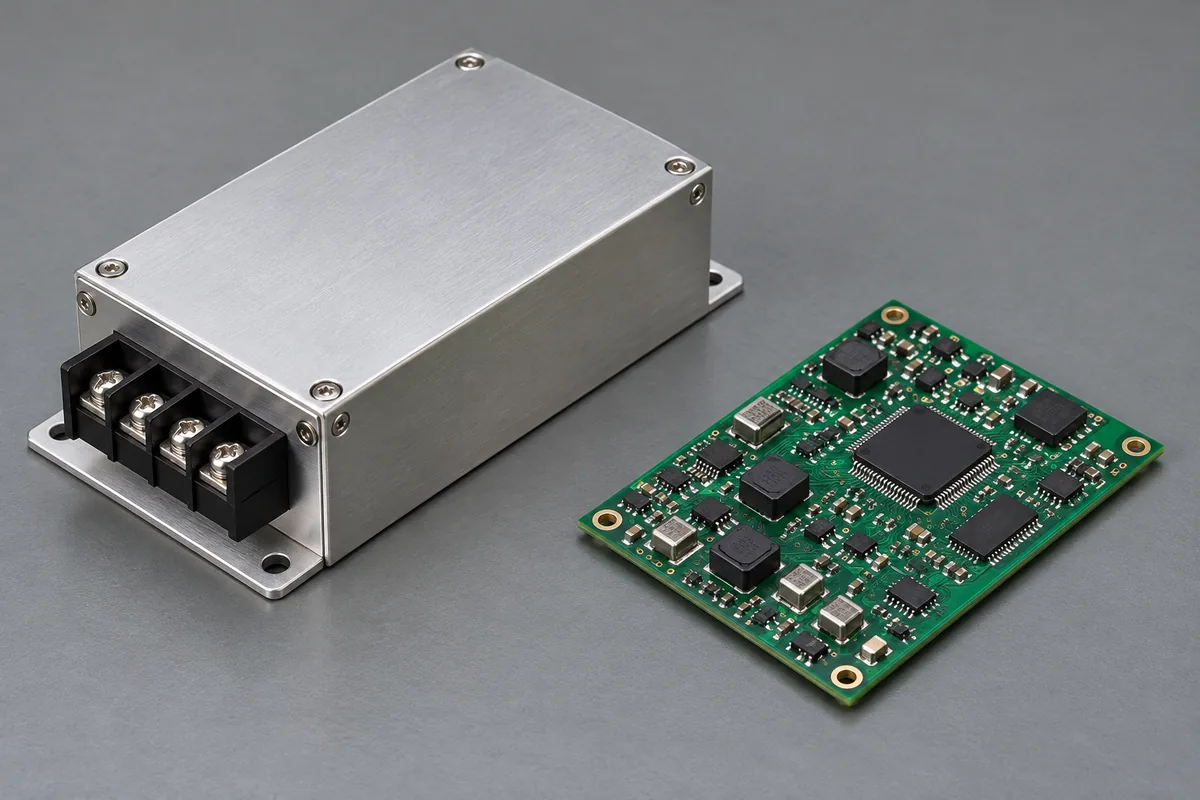
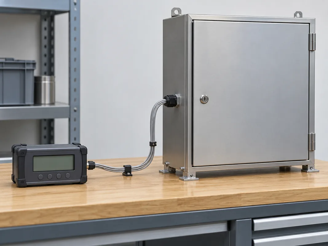
A practical industrial example is a bulk DC source serving several loads while one small board needs its own regulated rail. Identify the voltage at that board’s regulator input and the current its load actually draws. A catalog picture showing a separate supply and controller can illustrate those physical assemblies, but cannot establish whether a particular local stage is linear or switching.
Low input sets a regulation requirement
A linear regulator needs an input-to-output difference consistent with its documented operating conditions. Low-dropout describes a class of regulator behavior; it does not mean the required difference is zero or identical across products. Obtain the applicable limit at the required load and temperature, together with the other conditions needed for regulation.
The relevant minimum input is the voltage reaching the regulator during the states the application requires. Distribution drop can leave that point below the upstream supply terminals. Input ripple or a load event can reduce the instantaneous value further. An average reading above the output target therefore does not prove that sufficient headroom remains throughout the required interval.
Do not turn this observation into a universal rule to raise the bulk voltage. Other loads may be connected directly to that bus, and the regulator has a high-input thermal condition to satisfy. The effect of an adjustment has to be followed through both sides of the comparison. A setting that solves the lowest-input corner can make another operating state harder.
Also distinguish a functional limit from a damage limit. An absolute maximum input rating does not establish regulated operation across the full range below it. Similarly, a dropout entry does not establish noise rejection, transient performance, or startup behavior at that boundary. Use the exact definitions and conditions associated with each specification.
A required low-input interval can sometimes be addressed elsewhere in the architecture, such as by a supported change to distribution or the upstream source. That is an engineering change with its own effects. Editing the assumed minimum on a worksheet without changing the real circuit merely hides the condition that originally challenged regulation.
High input sets a different thermal burden
For a simple series linear regulator, the main pass-stage loss is approximately input voltage minus output voltage, multiplied by output current. Device operating current and other losses can add to that estimate. The relationship explains why the high-input, high-current state can be thermally demanding even though low input was the regulation concern.
Suppose a hypothetical stage supplies 5 V at 0.2 A from 24 V. Its approximate pass-stage loss is (24 − 5) × 0.2 = 3.8 W, while the load receives 1 W. These are illustrative numbers, not a product measurement or a claim that a particular package can dissipate 3.8 W. The heat still needs an implemented path into the surrounding equipment.
Doubling load current doubles that simplified voltage-drop loss at the same voltages. Conversely, reducing the difference can reduce loss while leaving less regulation headroom. This is why choosing a linear stage only from nominal output current can miss the governing constraint. Its current rating and installed thermal capability are separate pieces of evidence.
The local environment matters. A regulator beside a warm processor or inside a stagnant enclosure pocket does not experience the room temperature measured outside the cabinet. Board copper, mounting, heatsinking where applicable, nearby heat sources, and air movement determine the installed thermal path. A metal surface temperature and an air temperature are different observations; neither alone establishes the semiconductor’s permitted operating condition.
Use the selected component’s thermal and electrical documentation for the proposed assembly. A generic thermal resistance detached from its stated board and test conditions cannot establish an arbitrary installation’s capability. Thermal shutdown, where present, is a protective response rather than permission to operate continuously at an otherwise unsupported condition.
One hypothetical stage fails at opposite ends
Consider an invented design requirement for a 5 V local rail at a fixed 0.2 A load. Assume the candidate implementation needs at least 1 V of input-to-output headroom under all conditions in this example. Separately, suppose its established installation permits no more than 2 W of pass-stage dissipation. These are stipulated teaching assumptions, not manufacturer specifications or recommended allowances.
The assumed headroom requires at least 6 V at the regulator input. The simplified heat condition requires (input − 5) × 0.2 to be no more than 2 W. Solving that inequality gives an input no higher than 15 V. Under these assumptions, the acceptable input interval is therefore 6 V to 15 V, before any other product or load restrictions are applied.
Now give the fictional application a required input range of 5.5 V to 16 V. At the low end, only 0.5 V separates input and output, below the assumed requirement. At the high end, approximate pass-stage loss is 2.2 W, above the assumed installation allowance. A successful demonstration at 12 V input would show neither problem: it has 7 V of difference and about 1.4 W of pass-stage loss.
Raising the input everywhere cannot solve both failures. It can address the lower boundary while increasing high-end dissipation. Lowering the input has the opposite trade. The example needs a change to the source behavior, regulator implementation, thermal arrangement, load requirement, or conversion architecture. Which change is useful follows from the real constraints.
Keep the assumptions connected. If the actual load varies, its current belongs beside the corresponding input condition. If allowable dissipation changes with the environment, a single 2 W ceiling no longer describes every state. The example demonstrates two simultaneous constraints; it is not a substitute for the device’s complete operating envelope.
Operating duration changes the thermal question without removing the electrical one. A brief high-current state and a continuous high-current state can require different thermal evidence, while both still need valid regulation during their required interval. Do not grant a short event extra dissipation capability merely because it is short: any allowance needs the selected implementation’s transient thermal evidence and starting condition. Conversely, averaging a repeated loss over a long idle period can conceal a local temperature rise during the active interval. Preserve the actual duty history when the proposed solution depends on that distinction.
A switching front end can change the linear stage’s job
A switching preregulator followed by a linear stage is one possible architecture. The first stage can reduce a large voltage difference before the local linear regulator. The linear stage can then serve a narrower assigned role, provided its input range, headroom, output behavior, and installed thermal conditions remain supported. This combination is a proposal to assess, not an automatic optimum.
The intermediate setpoint needs both boundaries. Set it too high and the downstream linear stage retains an unnecessary dissipation burden. Set it too low and ripple, tolerance, distribution drop, or a transient can remove the required headroom. The average intermediate voltage alone cannot settle that trade. Establish which variations already belong in the documented bounds so they are not counted twice.
The switching stage contributes its own losses and output behavior. Reducing linear pass-stage loss does not by itself establish total system efficiency. Compare input power for the complete proposed chain at matching load states, or use applicable data with clearly stated assumptions. Keep that result separate from any claim about the complete mains-powered equipment.
Noise performance also needs evidence at the relevant boundary and frequency range. A linear post-regulator does not automatically erase every disturbance from its source, and a switching stage is not automatically unsuitable for precision electronics. The load’s permitted error, the candidate regulators, their operating points, and the installed distribution determine whether the result is acceptable. No universal quiet-versus-efficient ranking resolves those details.
There are operating consequences beyond steady loss. The added stage can change startup, disable, fault recovery, and behavior with an already energized output. The local rail may also need to remain available while other machine loads are off. Preserve those requirements when considering a hybrid arrangement, rather than judging it solely from a favorable normal-running calculation.
Different industrial loads can justify different arrangements
A modest local load with a suitable input range and an adequate installed heat path can be a sensible linear-regulation application. A larger voltage reduction or current demand can make its dissipation less attractive. An eligible switching implementation can address that conversion duty, but still needs to meet regulation, transient, noise, thermal, and control requirements. Neither category bypasses application evidence.
Compare alternative architectures at equal service. A rail allowed to turn off during a source disturbance is different from one required to remain regulated. A reduced current commitment differs from supporting the original load. A larger heatsink changes the occupied assembly and thermal path. These can be legitimate proposals, but their consequences should remain visible instead of being presented as interchangeable fixes.
The comparison can also be local within one machine. Bulk actuator power and a small measurement rail need not use the same regulation approach. Applying one solution everywhere can simplify a purchasing list while imposing unnecessary loss on one rail or leaving another’s performance unmet. Allocate the conversion duty before comparing component count or package size.
For complete AC-input supplies, return to complete-unit evidence: rated output under the intended input and environment, measured behavior, installation conditions, and the machine’s requirements. For a downstream linear stage, retain the low-input headroom and high-input heat checks together. The practical value of comparing linear and switching power is finding an arrangement that satisfies both ends of the required duty, rather than winning a category argument at one convenient operating point.