A buck converter steps voltage down; a boost converter steps it up. In server DC-DC power design, that distinction should be applied to the voltage reaching the converter and the rail required by its load. A buck stage is a possible route when the input remains sufficiently above the required output. A boost stage addresses an input below the required output. If the input must move through both relationships, comparing a buck-only design with a boost-only design leaves part of the job unanswered.
The difficult case is often a rail close to its upstream bus, rather than a large voltage conversion ratio. A nominal bus label can conceal conditions above and below the desired rail. Start with that relationship, then examine exact converter limits. There is no useful universal winner between buck and boost when they perform different voltage-conversion tasks.
Locate the conversion stage before comparing its topology
A server can contain several power-conversion boundaries. The facility source feeds the server power arrangement; an internal bus distributes power; local converters supply individual board circuits. The input to a local regulator is the voltage at its own terminals. It is not automatically the voltage on a PSU label or the voltage measured at a distant distribution point.
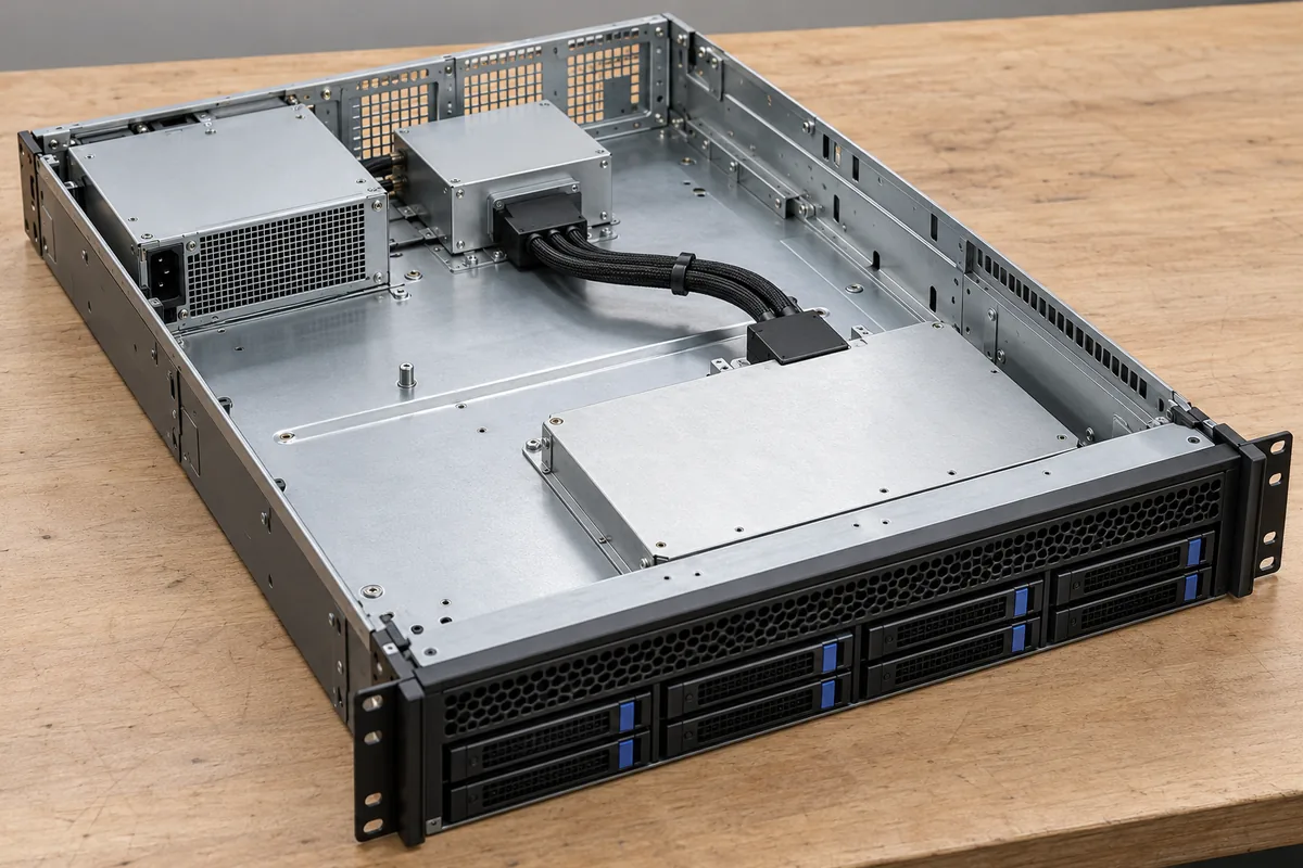
For a board-level design, identify the source, input and return path, converter, output distribution, and receiving load. Include any intermediate conversion stage. A statement that a server distributes one bus voltage does not establish that every local converter receives that bus directly. Two regulators on the same board can have different input sources and different conversion jobs.
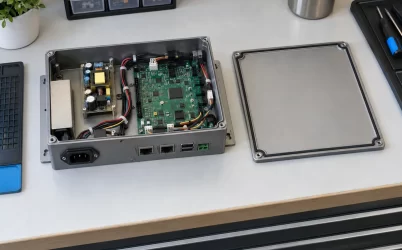
The physical arrangement helps explain why that boundary matters. Local regulators can sit near consuming circuitry while the source reaches them through a connector, plane, cable, or distribution assembly. Those paths belong to the installed design. Their voltage drop can affect which input condition the converter encounters, but changing topology does not remove the need for an adequate current path.
Distinguish ordinary non-isolated step conversion from a requirement for galvanic separation. A basic buck or boost label does not establish an isolation barrier. If the load needs isolation, that requirement changes the eligible implementations. Likewise, adding voltage-conversion capability does not establish processor command support, sequencing compatibility, fault containment, or an approved server interface.
A nominally equal bus and rail can need two directions
Consider a hypothetical supporting rail requiring regulated 12 V at its stated output boundary. Assume the documented application requires its converter input to operate from 10 V to 14 V. These are invented design conditions, not a specification for a server or commercial converter. They deliberately place the required input below, equal to, and above the desired output.
At 14 V input, the task is step-down conversion. At 10 V, it is step-up conversion. Both states belong to the assumed requirement. A converter that supports the first state but not the second is not made suitable by a favorable efficiency result at 14 V. A converter that supports the second but cannot regulate as required at 14 V has the opposite gap.
TDK-Lambda’s July 31, 2020 explanation of buck, boost, and buck-boost converters establishes this directional distinction: buck reduces voltage, boost increases it, and the buck-boost arrangement discussed can produce an output above or below its input. Its simplified circuits are non-isolated examples. The article supports classifying the conversion job; it does not establish that every device bearing one of those names supports the hypothetical range.
| Hypothetical input relative to the required rail | Conversion task | What remains to establish |
|---|---|---|
| Input above output | Step down | Exact regulator operating limits and required headroom |
| Input below output | Step up | Exact regulator range and available output at that input |
| Input crosses the output value | Both directions within the required operating range | Supported implementation, polarity, crossover behavior, and applicable conditions |
The table is a direction filter, not a compatibility matrix. It excludes a mistaken conversion role before detailed design work. It does not supply a circuit, identify an orderable module, or establish output current. Those findings require the exact candidate documentation and implemented conditions.
Do not discard the below-output state merely because the source spends most hours above it. If continuity is required there, that state can determine eligibility. If the system explicitly permits the rail to stop below a defined source condition, the design requirement is different. State that allowed behavior rather than quietly claiming regulation across a range the selected converter cannot support.
Equality is a condition to investigate, not a guaranteed operating point
The phrase step-down suggests a simple inequality, but a real buck implementation needs more information than input greater than output. Review its documented duty-cycle limits, voltage drops, operating mode, and output capability under the proposed conditions. A source only slightly above the requested rail may leave a different operating situation from the comfortable voltage ratio used in a typical efficiency plot.
Similarly, a step-up implementation’s operating input range does not by itself establish a regulated output when the source reaches or exceeds the requested output. Determine what the candidate actually does in that condition. Do not treat the existence of an input-to-output electrical path, where present in a particular circuit, as equivalent to active regulation at the target voltage.
For a design intended to cover both sides, the transition region deserves explicit evidence. Identify the candidate’s supported operating modes and the applicable input, output, load, and temperature conditions. A converter may change its control behavior as the voltage relationship changes. The topology name alone cannot establish the output deviation or transient behavior during that change.
Polarity is another independent check. Buck-boost terminology can describe different circuit arrangements, including implementations whose output polarity differs from their input reference. A supporting rail requiring a positive output relative to its defined return needs an implementation supporting that relationship. Do not select from a magnitude-only comparison or assume that every buck-boost circuit is non-inverting.
Nor does a converter’s ability to step voltage in either direction make it bidirectional in power flow. Supplying a load and accepting energy returned from that load are different functions. A design requiring reverse-energy handling must obtain evidence for that behavior separately. The word boost does not establish a safe destination for energy returning from another powered rail.
Follow the actual crossing event through the source and load
Return to the fictional 10 V to 14 V input requirement. It could describe a slowly changing source, a bounded disturbance, or a transition between source arrangements. Those histories create different questions even though the endpoints are identical. Identify the event the real application must survive before treating a static input-range entry as the complete answer.
For slow movement, the concern is sustained regulation and component duty throughout the required range. For a rapid change, output deviation and recovery also matter. The allowed excursion comes from the actual receiving circuit, not a universal server tolerance. A demonstration at one fixed input does not establish the response to movement through the transition region.
Repeated crossings are another distinct history. An input averaging near the target can move above and below it several times as the source and load vary. Describing only the average discards those events. Keep the relevant variation and time scale in the application record, then seek evidence for the selected implementation under that history. This does not imply that repeated crossings necessarily cause a fault or that a particular control strategy is required. It identifies the condition that an isolated high-input test and an isolated low-input test leave unexamined. A stable result on each side is useful evidence, but it is not the same observation as stable behavior while moving between them.
The converter input and load output need separate observation boundaries. If the upstream bus appears healthy but the converter input falls during a demand change, investigate the intervening path. If the converter output is acceptable while a distant load terminal falls outside its permitted range, downstream distribution remains relevant. Neither finding can be resolved simply by renaming the converter buck-boost.
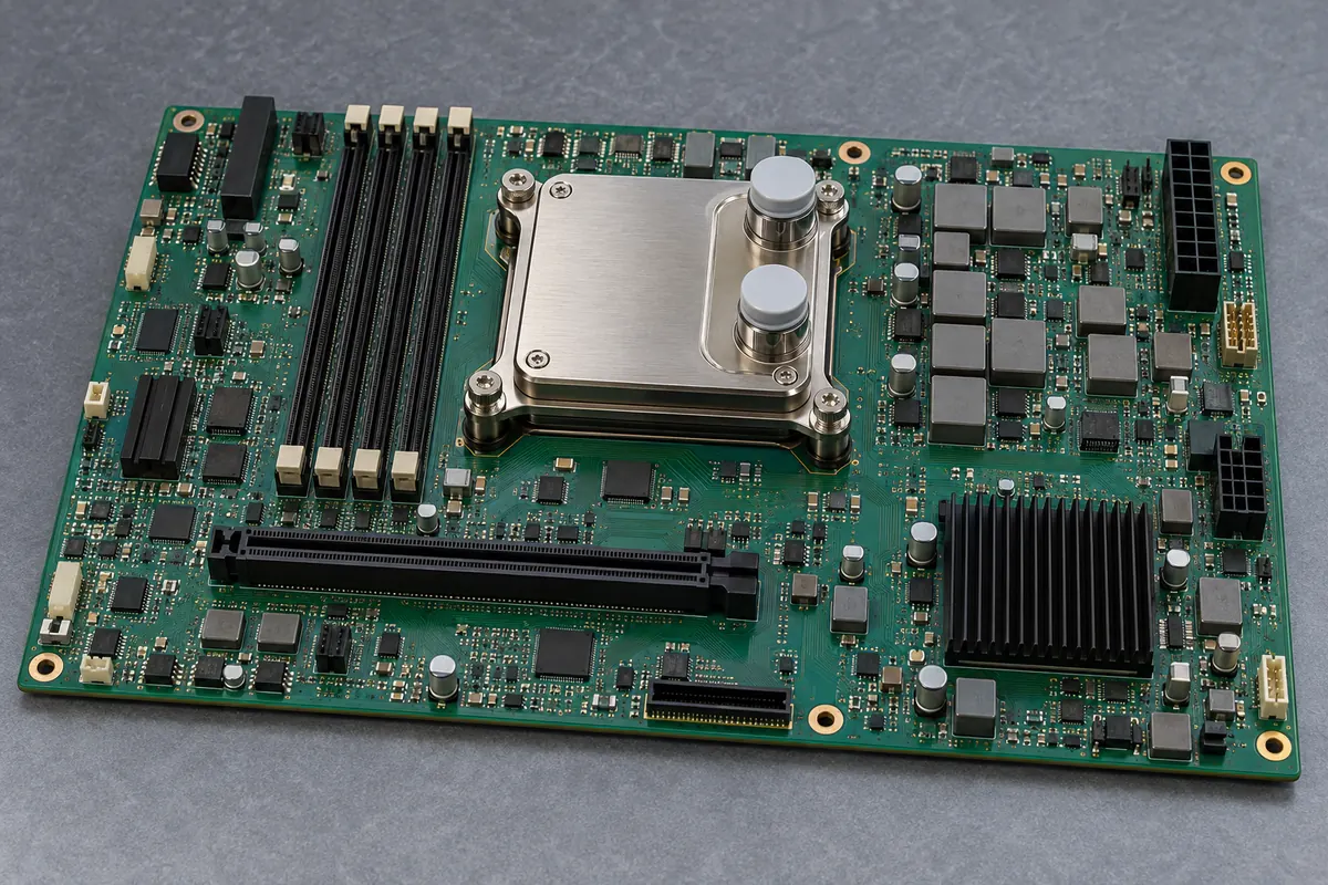
Input current also has to support the assigned output duty. Raising voltage does not create power, and a source can encounter current or thermal limits as operating conditions change. Keep this issue separate from conversion direction. A topology capable of reaching the target voltage may still lack the required deliverable output under the source condition that prompted its selection.
Startup can begin on either side of the target in the assumed application. Determine whether the candidate is documented to start with the actual input, load, and any existing output voltage. Successful operation after a different startup does not establish that initial condition. Enable logic and the host’s power sequence must preserve the conditions on which the converter’s behavior depends.
Keep required event duration visible. If the output must remain available only for a defined interval during a source disturbance, the architecture may include a supported energy-storage arrangement. That is a different proposal from continuous conversion across the whole source range. Stored energy, converter direction, and source recovery should not be blended into one unspecified ride-through claim.
Extra conversion capability should earn its place
If the real input remains within a documented step-down operating region, an eligible buck implementation may satisfy the rail without a design intended for both directions. If the real task is entirely step-up, assess eligible boost implementations. When the required relationship crosses, a suitable buck-boost implementation or a revised power architecture can be considered. The comparison follows the job rather than an abstract ranking.
Broader capability is not automatically free. Compare the actual candidates’ external components, installed space, loss behavior, thermal conditions, control requirements, and supported modes. Avoid assigning a universal efficiency penalty or cost advantage to a topology category. One manufacturer’s conceptual comparison cannot settle the purchasing result between unidentified implementations.
There is also an architectural alternative to widening the converter’s role: change where the local rail is sourced, where permitted by the server design. A different supported upstream rail might keep the input consistently on one side of the target. That change can introduce distribution, standby, sequencing, or capacity consequences elsewhere. It needs a complete system comparison rather than a claim that one voltage label is inherently better.
For example, moving a supporting load onto a source that disappears during standby can solve the normal running conversion ratio while removing a function that must remain available when the server is off. The converter might work perfectly in its new voltage range and still serve the wrong operating states. Preserve the load’s role alongside its voltage requirement.
Component substitution should preserve the relevant relationship as well. A replacement with the same nominal output and higher current can still have a different required input margin or unsupported crossover condition. Likewise, a reference board’s favorable result belongs to its actual implementation. Retain the input history and operating conditions needed by the rail instead of reducing the requirement to output volts and amperes.
In the hypothetical 12 V rail, the decisive fact is that the required input moves from below 12 V to above it. A buck-only or boost-only comparison therefore describes only part of the assigned conversion job unless the system explicitly permits a different outcome. For a real server, establish that relationship at the converter terminals first. Then choose an implementation whose documented behavior covers the required direction, transition, and load states.