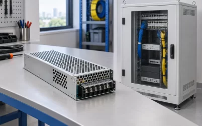
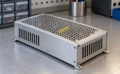
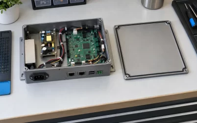
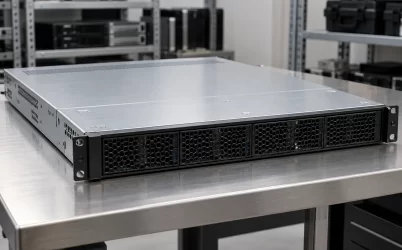
A 2200W 1U CRPS power supply is a high-output removable module intended for a compatible one-rack-unit server, not a standardized replacement defined by those three labels. Powernexu lists one 2200W CRPS body at 185 mm long and another at 265 mm long; both are 40 mm high. That 80 mm depth difference can decide whether a module reaches the power-distribution board, clears the chassis interior, or can be removed for service. If the search is for a replacement, begin with the approved host part and bay drawing. If it is for a new 1U design, choose the PSU and bay together rather than treating 2200W as a drop-in specification.
One rack unit does not define the depth of its power bay
A 1U server occupies about 44.45 mm of nominal rack height. The PSU must live inside the smaller usable interior after the chassis sheet metal, rails, clearances, vibration allowances, and air path have taken their share. A 40 mm-high CRPS body may be mechanically plausible in that envelope. It does not follow that every 40 mm-high module can enter the same bay. Width, insertion orientation, and especially the distance from the rear opening to the mating connector are separate dimensions.
Consider two modules with the same nominal 2200W output, 73.5 mm width, and 40 mm height. If one body is 185 mm long and the other 265 mm, the latter needs 80 mm more longitudinal room before allowing for handle geometry, connector engagement, rear cable clearance, or adjacent components. In a dense 1U host, that extra distance may be occupied by a fan wall, riser, drive backplane, processor heatsink, or the PDB itself. A seller’s description of both products as “1U CRPS” says little about that collision.
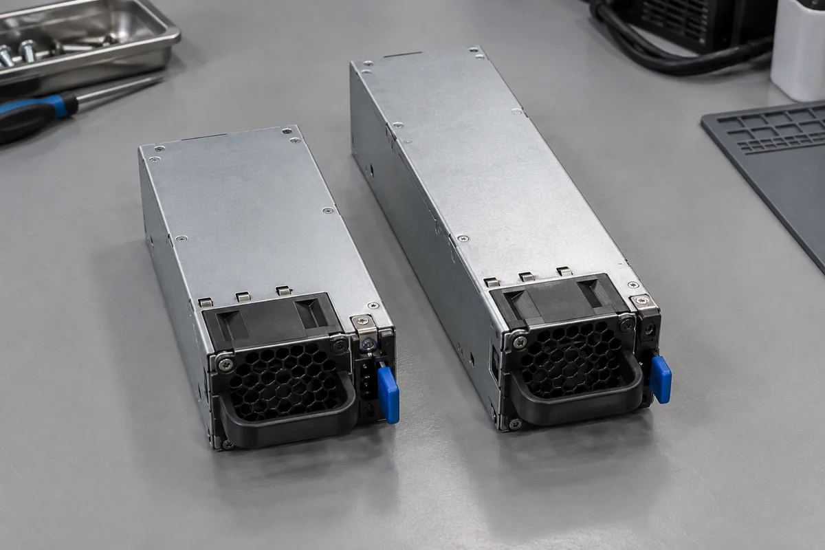
The inverse is possible too. A chassis designed around a long-body PSU may position its PDB deeper than a short module can reach. A shorter enclosure is not automatically the safer substitute. It may lose the guide engagement or leave its contacts short of the blind-mate connector. The useful measurement is not simply the bare casing length; it is the installed distance from the module’s mechanical stop to the electrical mating plane.
For an existing machine, photograph the installed module’s label, latch, handle, and connector end, and read the chassis or server service documentation. A loose module on a bench cannot show the rack rail, rear door, and extraction obstructions that determine whether a hot-plug replacement remains serviceable.
The two 2200W Powernexu examples occupy different mechanical territories
Powernexu’s published CRPS2200D2 product specification describes a 2200W Platinum CRPS module measuring 185 × 73.5 × 40 mm. The CRPS2200CL product specification describes a 2200W Titanium long-body module measuring 265 × 73.5 × 40 mm. Both pages identify a 12V main output and front-to-rear airflow. The manufacturer’s Great Wall CRPS model listing independently shows those two different lengths. These are examples of the physical split within one power rating, not evidence that either model fits a particular 1U server.
| Published model | Body length | What the difference changes |
|---|---|---|
| CRPS2200D2, 2200W Platinum | 185 mm | Candidate only for a host designed for its exact short-body mechanical and electrical interface |
| CRPS2200CL, 2200W Titanium | 265 mm | Requires a deeper bay and the corresponding guide, stop, mating and cooling arrangement |
Neither efficiency classification proves a chassis fit. Titanium and Platinum describe efficiency programs under defined test conditions, while 185 mm and 265 mm describe the published enclosure lengths. Nor does the common 12V output establish identical pin assignments, standby behavior, enable logic, current-share implementation, management commands, or connector keying. Even two modules whose outer dimensions match may be incompatible at the PDB.
The CRPS2200D2 page publishes an AC input range and a high-voltage DC input range. The CRPS2200CL page does not specify an input range in the data displayed there. That asymmetry matters: a comparison chart assembled from neighboring products would be unsafe. Obtain the exact input and output curves for the exact offered revision before assuming full output at the site’s line voltage. Avoid converting a family-level claim into a model-specific promise.
The connector datum matters more than the photograph of the casing
When a removable CRPS unit slides into a 1U server, the last few millimeters establish both mechanical retention and electrical contact. The chassis guides control pitch and alignment; the module latch establishes its final position; the PDB connector receives the power and control contacts. Changing body length can move that engagement point even if the rear panel seems to accept the module. An installer should not apply extra force to overcome resistance from a mismatched connector or displaced PDB.
For new chassis development, place the module’s insertion axis, guide datum, latch stop, and PDB mating plane on one controlled drawing. Leave clearance for the full handle swing and straight withdrawal path. Then overlay the 1U server’s fan wall, processors, memory, storage cage, and PCIe riser. A paper cutout of a 185 mm rectangle is not enough: connector depth, inlet grille, cable bend radius on the PDB side, and manufacturing tolerances can consume the space that appears available.
In a replacement project, the comparison is more constrained. The original system may have an approved spare list or firmware policy. The exact model, revision, connector, airflow orientation, and management implementation may be coupled to that host. A nominally compatible body with a different sense pin or standby rail could fail before the main output is ever enabled. A server’s 1U height tells a buyer nothing about those assignments.
The PDB must also be able to carry the current associated with a 2200W-class 12V source. Dividing 2200W by 12V suggests an order of magnitude near 183 A for an idealized main-output estimate; actual model output limits, standby allocation, voltage tolerance, and operating conditions require the manufacturer’s data. That estimate is useful only to explain why contact resistance and copper layout matter. It is not a new rating for either cited model or permission to insert one into an existing board.
A 1U airflow path can make a nominal 2200W module unusable
Both cited Powernexu examples list front-to-rear airflow, but a chassis still has to deliver cool enough air to the correct side of the PSU at the required pressure. In a 1U server, a small gap beside a module can become a bypass path. Air may travel around the supply instead of through its internal heat-generating parts. A misplaced seal, empty PSU bay, blocked intake, or dense rear cable bundle can change the result without changing the PSU nameplate.
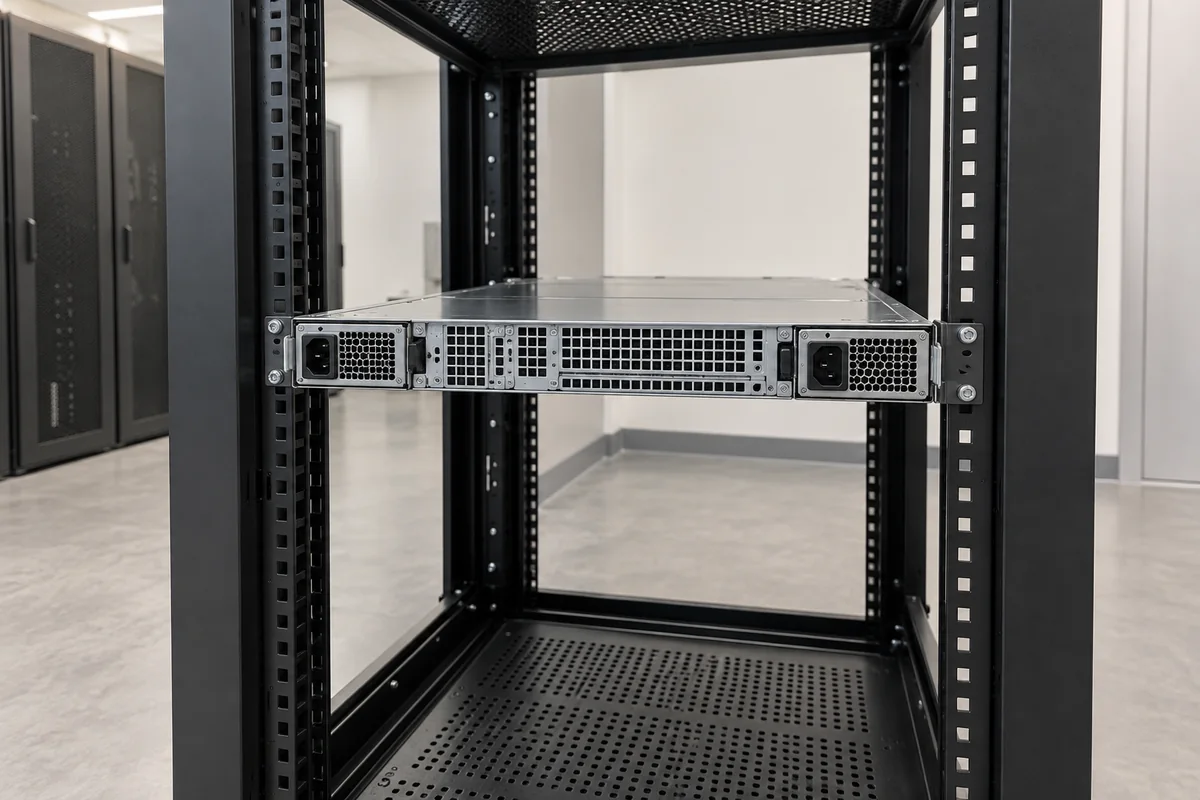
The long-body module occupies a different span of the server’s internal pressure path than the short one. Its inlet and exhaust positions, relationship to the host fan wall, and proximity to warm downstream components need assessment in the actual chassis. The short body may leave more internal length for other components, but it is not automatically cooler. Fan design, airflow direction, efficiency at the actual load, and chassis pressure determine the thermal outcome.
At 2200W output, even high efficiency leaves meaningful conversion loss. If an illustrative converter operated at 94% efficiency while delivering 2200W, the calculation 2200 ÷ 0.94 − 2200 gives about 140W of internal loss. This is a hypothetical engineering example, not a published efficiency point for either model. At a lower operating load, both the absolute loss and efficiency may differ. The point is the cooling burden concentrated in one narrow 1U power bay, especially after one module takes over a protected load.
A shelf photograph rarely reveals the air’s actual path. A useful chassis review observes the PSU inlet temperature, exhaust temperature, module fan behavior, and neighboring component temperatures under representative workloads. The inlet should be measured where the PSU takes air, not inferred from a room sensor several meters away. A door grille, rack blanking panel, or bundle directly behind the hot-plug handles may be the limiting feature.
2200W is a module rating, not a promise of 4400W protection
Many searches for a 2200W 1U CRPS unit lead to a two-module server. Two 2200W labels can describe a 1+1 arrangement in which either module is expected to support the permitted server load after its partner fails. They can also appear in a combined-capacity arrangement that needs both modules to maintain a higher load. Those modes are system properties, not consequences of the PSU labels. A 1U chassis must have the PDB, control logic, and cooling needed for whichever mode it claims.
For a protected 1+1 service state, compare the server’s approved maximum demand with the usable output of one module at the actual AC or DC input and inlet conditions. The remaining module then has to supply that load through the PDB without its contacts or distribution branches exceeding their limits. A long-body 2200W module may offer the right nameplate rating yet be wholly unsuitable for a host wired around a short-body unit. Conversely, installing a short-body unit in a long-body bay can defeat the mechanical and electrical connection before capacity is relevant.
The electrical behavior during removal matters to a serviceable 1U server, but it is not necessary to turn this article into a general hot-swap tutorial. The practical question here is narrower: is the exact 2200W module an approved physical and electrical member of this bay, and can the surviving power path carry the host’s permitted load? Answering only the second question leaves the central 185-versus-265 mm distinction unresolved.
Resolve the 1U fit with a host-specific mechanical comparison
For an existing 1U server, start with its service manual and installed spare number. Record the bay’s usable depth, the connector location relative to the chassis rear, the original module length, the guide and latch geometry, and the extraction clearance at the back of the rack. Read the offered PSU drawing beside those facts. If the chassis calls for a 185 mm body, the 265 mm CRPS2200CL cannot be treated as a substitute merely because it has the same height and wattage. If the design calls for a long body, the 185 mm CRPS2200D2 is not established as interchangeable either.
For an OEM designing a new 1U platform, the decision can be made earlier. A compact module may preserve internal room for a fan wall or storage, while a long-body bay allocates more chassis depth to the supply and may alter the positions of those other assemblies. The right drawing also reserves space for both modules if redundancy is required, their independent removal paths, the PDB, and the rear power cords. That is a packaging decision with electrical and thermal consequences, not a ranking in which shorter or longer is universally better.
Ask the supplier for the exact mechanical drawing and connector specification tied to the offered revision. Ask the host vendor whether that revision is approved, especially when replacing an OEM module. Where a site uses low-line AC or an unusual DC feed, request the model’s full-output conditions rather than assuming a published input range guarantees 2200W throughout it. None of those requests should be replaced by a generic “1U CRPS” label.
The concrete answer is therefore conditional but not vague. A 2200W CRPS unit can serve a 1U server when its complete mechanical envelope, mating interface, input conditions, airflow, and host approval match that server. Powernexu’s published 185 mm and 265 mm examples show why the first measurement cannot be skipped: they share the headline rating and nominal height, yet occupy different depth classes. For a replacement, the exact host-approved part wins; for a new design, the 1U bay is designed around the chosen module rather than the other way around.