A floating DC power supply output controls the voltage between its output terminals without deliberately fixing either terminal to earth through a direct reference connection. A grounded output has an intentional earth reference. The useful comparison is not which arrangement is universally safer or quieter. It is whether the source and everything connected to it support the required voltage between terminals and the required voltages from those terminals to earth.
Those are different requirements. A supply delivering a modest differential voltage can operate in a circuit whose entire output sits above earth potential, if the exact product permits that use. The differential rating alone does not authorize the offset. When comparing floating versus grounded DC power supply outputs, keep the output-to-earth operating boundary visible before deciding where to establish a reference.
One output has more than one voltage relationship
Label the two DC terminals positive and negative, and identify the chassis and earth reference separately. The load normally receives the difference between the DC terminals. A terminal-to-earth measurement describes another relationship. Calling the negative terminal “zero volts” identifies a chosen circuit reference; it does not establish that the terminal is at earth potential.
Consider a hypothetical source maintaining 24 V between its terminals. If its negative terminal is intentionally held at 60 V above earth by a surrounding circuit, its positive terminal is at 84 V above earth. The load still receives 24 V. These values illustrate subtraction and addition, not a supported configuration or rating for a commercial supply. Nothing about the 24 V differential value establishes permission to operate either terminal at those earth-referenced potentials.
The same distinction appears with a negative offset. If the negative terminal in an imaginary circuit is 30 V below earth and the differential output is 24 V, the positive terminal is 6 V below earth. Both terminals can be below earth while the positive terminal remains positive relative to the negative terminal. Terminal names describe their relationship to one another; they are not an absolute voltage coordinate.
For clarity, record the potential of each output terminal relative to the same earth reference. An application using the phrase common-mode voltage should also state its definition and reference point. Do not assume that a common-mode figure quoted for a measurement input has the same meaning or allowable range as a supply’s permitted output-to-earth voltage.
A conceptual drawing should therefore show three distinct objects: the two-terminal source, its load circuit, and the earth or chassis reference. An insulated-looking enclosure or a separated pair of output wires cannot establish the internal relationship between those objects. The exact connection diagram and operating specifications supply that information.
Floating capability needs its own operating envelope
The output voltage adjustment range and the permitted earth-referenced operating range answer different questions. The first describes what the source can supply between its terminals. The second concerns the potential the output circuit may have relative to other parts of the equipment. A product suitable for ordinary isolated output operation is not automatically suitable for an arbitrary imposed bias.
Matsusada Precision’s manufacturer explanation of floating ground distinguishes a floating reference from earth and describes specially designed floating supplies for biased applications. It also cautions that floating configurations vary by model and are not guaranteed for every unit. Its examples establish why exact product permission matters; they do not authorize modification of an unidentified industrial supply.
Look for documentation explicitly covering the intended output-to-earth operation. Preserve the named terminals, permitted polarity, operating conditions, and any restrictions on connected interfaces. If the manufacturer provides a value called isolation voltage, determine what that value actually specifies. A brief dielectric withstand test and a permitted continuous operating potential are different descriptions; one cannot silently become the other.
Likewise, input-to-output isolation and output-to-chassis behavior should not be merged into one rating. The source can contain several relevant insulation boundaries and internal connections. A general approval mark or an isolated-output description does not by itself identify which boundary supports the proposed earth offset. Resolve the required relationship from the exact documentation, seeking manufacturer clarification where its meaning remains uncertain.
The operating states matter as well. Define the intended terminal-to-earth potentials during normal operation, startup, shutdown, and relevant faults. A normal-state offset below a documented limit does not establish that every transition remains within that limit. Conversely, a supply with more differential output capacity does not necessarily provide more permissible offset. These are independent entries in the design requirement.
This changes product comparison. Two supplies with the same output voltage and current can differ in supported floating operation. A candidate with excellent regulation may still lack the required earth-referenced operating evidence. That is an unresolved application boundary, not proof of poor product quality. Buying more output watts would not resolve it.
The attached equipment can establish the reference
A supply does not remain electrically alone after installation. Its output connects to a load, and the load may connect to a controller, measurement instrument, communication interface, or another source. Those connections can introduce a reference that is absent at the supply’s own terminals. The installed output’s relationship to earth must include those paths.
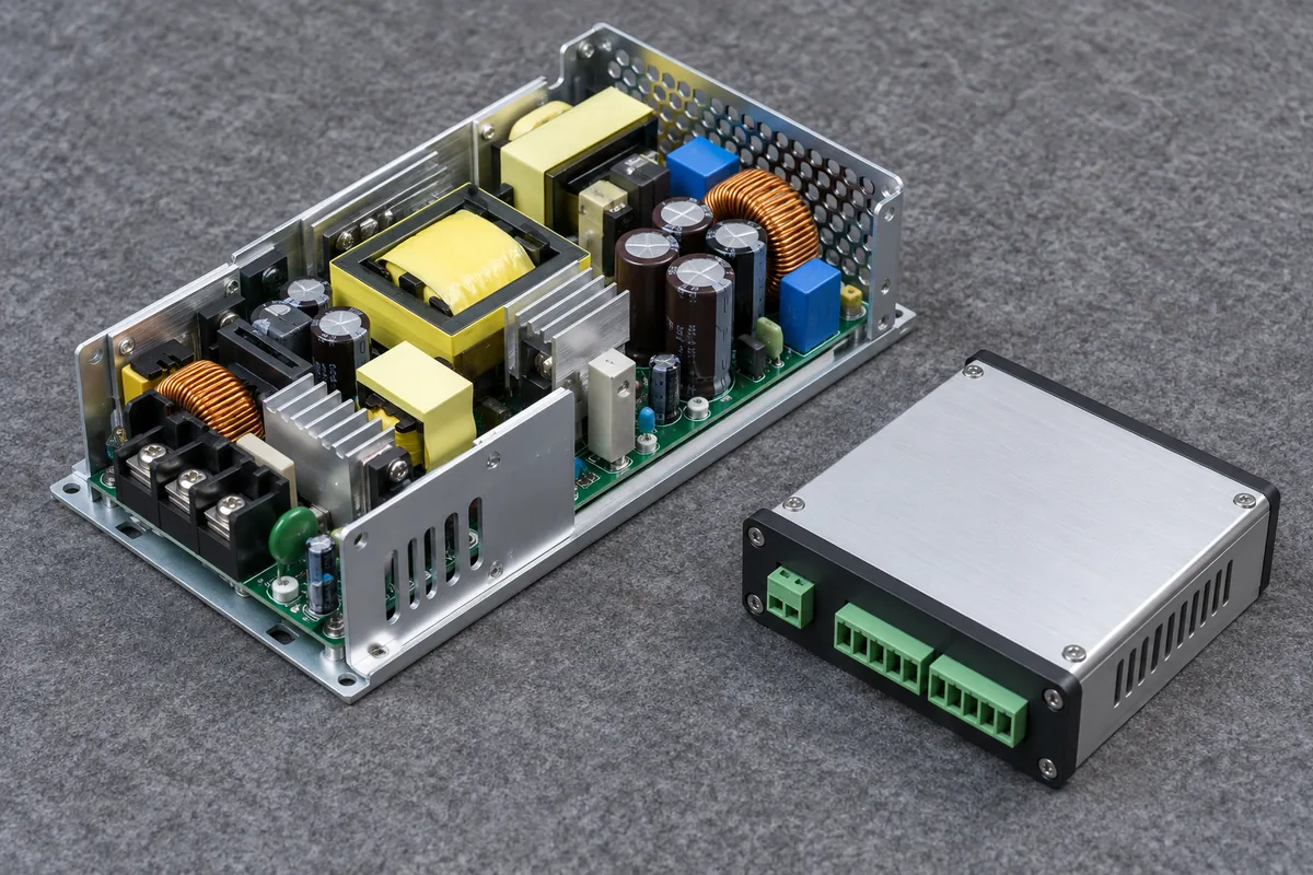
For a hypothetical instrument, suppose the supply feeds an isolated load during one operating mode. In another mode, an interface connects the load’s circuit common to an earth-referenced device. If that interface provides a conductive connection, the second mode has a different reference arrangement. The source itself has not changed. Whether the connection is permitted depends on both devices and the intended circuit.
Do not assume every instrument terminal is isolated, or that every communication port establishes a direct earth bond. Read the actual interface documentation. An instrument can have a limited permitted input-to-earth potential even when it measures a small voltage between two inputs. Its differential measurement range does not establish its common-mode capability, just as the supply’s differential rating does not establish its floating range.
Measurement equipment consequently belongs on the circuit drawing. Identify which observation connection reaches which node and whether it adds a conductive earth path. A measurement arrangement that establishes an unintended reference can change the object being observed. Selecting appropriately rated measurement methods is work for qualified personnel; disconnecting protective earth from an instrument or enclosure is not a way to obtain a floating measurement.
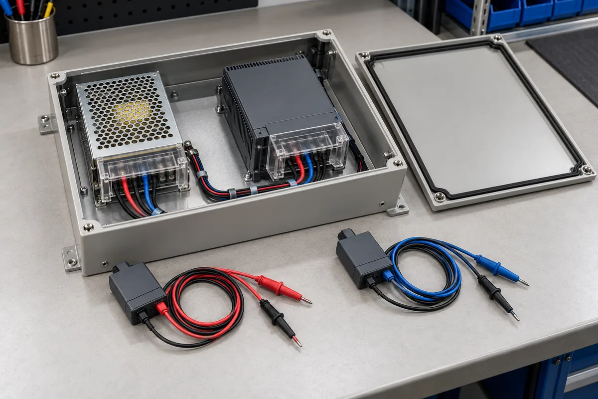
Include ordinary control accessories, too. Remote programming, monitoring, and sensing interfaces may have model-specific references and isolation. A power output permitted to float does not imply that every control connector tolerates the same potential. The narrowest applicable interface boundary can limit the complete arrangement even when the main power terminals meet their own specifications.
Optional connections deserve separate operating entries. An assembly may be used alone in production, connected to a service computer during maintenance, and attached to a recorder during development. The applicable reference paths can differ among those states. A successful isolated-load demonstration does not cover the service connection merely because the DC load remains unchanged. Identify which connections are present when the imposed offset exists and which are permitted only after that condition has been removed under the approved procedure. This keeps an accessory restriction visible without pretending that every accessory must support every operating mode. It also prevents an intermittent service connection from becoming an unrecorded permanent change to the reference arrangement.
There is a useful distinction between discovering a reference and choosing one. A measured terminal-to-earth voltage can reveal the present circuit state, but it does not establish the permitted operating range or prove how strongly that node is referenced. The documented topology and suitable measurements answer different parts of the question. A surprising reading should lead to investigation, rather than an automatic jumper between output and chassis.
Adding source voltages also changes earth-referenced stress
Series and biased-source arrangements make the two voltage boundaries especially visible. Treat them as separately engineered applications requiring explicit manufacturer support. The fact that two outputs are isolated does not establish permission to connect them in series. Protection, reverse voltage, interfaces, sequencing, and the connected load can impose additional requirements beyond the arithmetic.
For illustration only, imagine three ideal 24 V sources arranged in a permitted series circuit, with the lowest node referenced to earth. The successive node potentials would be 0, 24, 48, and 72 V relative to earth. Each ideal source still spans 24 V. The highest source would nevertheless have terminals at 48 and 72 V relative to earth. Differential output ratings alone say nothing about whether real products support those potentials.
Moving the intentional reference changes those earth-referenced values while leaving the ideal differences unchanged. If the 24 V node were instead the reference in that mathematical example, the four node potentials would become −24, 0, 24, and 48 V. This is a coordinate comparison, not an instruction to relocate an operating bond. The real installation must support its selected reference and the resulting potentials throughout the system.
The example explains why an identical replacement is more than a matching voltage label. The upper and lower positions can impose different output-to-earth requirements on otherwise similar sources. An accessory suitable at the lower position may not be suitable at the upper one. Retain the position and reference information with the exact product and interface requirements instead of treating every source as an independent 24 V object.
Shutdown can change which source is producing voltage while connections remain in place. That raises questions about voltage imposed on an inactive output and its attached interfaces. Do not infer a real product’s reverse-voltage tolerance or protective response from the ideal series example. A design needing that behavior requires exact product evidence; the simple node calculation only identifies where further questions arise.
Reference choice follows the circuit’s actual purpose
An intentional earth reference can provide a defined relationship for connected equipment when the approved system requires one. Floating operation can support applications that require a different reference or separation, within the chosen products’ limits. Neither choice establishes universal immunity, absence of noise, or safety. Protective earthing of exposed conductive parts remains a separate requirement of the equipment’s protection design.
For an ordinary control cabinet, the unresolved question may be whether the controller requires a particular DC common. For a biased measurement assembly, it may instead be whether the entire output and its control interfaces can operate at an imposed potential. These applications should not receive the same answer merely because both use an isolated converter. Their intended relationships to earth differ.
A supply with a removable reference link also needs its exact instructions followed. The existence of a link does not authorize removing it on every unit or for every application. Matsusada’s FAQ explicitly warns that changing the described shorting arrangement can affect safety and EMI performance. That warning is a reason to preserve model-specific instructions, not a general procedure for floating other products.
The comparison becomes concrete when both voltage requirements are written together: the load needs a stated differential output, and each output terminal must remain within its permitted earth-referenced operating conditions. Add the limits of the load and connected interfaces. A supply satisfies the first requirement by regulating its output; the complete circuit satisfies the second only when its actual references and supported operating limits agree.