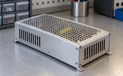
GW-GSP1600W-48 is Great Wall’s 1600 W, nominal 48 V single-output enclosed AC/DC supply. The manufacturer rates its 48 V version at 33.5 A and lists 90–264 Vac or 127–370 Vdc input. A search for this exact model is usually a specification or sourcing question, but the product page alone does not explain the operating conditions behind those numbers. The distinguishing issue is how its adjustable output, remote sense, control signals, and documented parallel-sharing rules behave in a fixed 48 V cabinet. This is a chassis-mounted industrial supply, not a blind-mate CRPS cartridge or a 48 V-input rectifier.
The 48 V model’s published operating envelope
The Great Wall GSP1600W series datasheet, dated July 8, 2025, identifies the exact 48 V model and its 1600 W rating. It lists 33.5 A rated output, 92% full-load efficiency, a 280 × 127 × 41 mm enclosure, a built-in speed-controlled fan, and an operating-temperature range of −25°C to +70°C subject to its derating curve. The product is described as a fully digital, single-output enclosed supply with active power-factor correction. These are model-specific figures, not generic specifications for 48 V supplies.
At 48 V, 33.5 A multiplies to 1608 W, slightly above the rounded 1600 W nameplate. That arithmetic does not grant a continuous 1608 W operating allowance. Use the manufacturer’s 1600 W rating and any applicable derating, especially when changing the output set point. The 92% figure is a stated full-load efficiency under the datasheet’s test convention: unless otherwise specified, parameters are measured at 230 Vac input, rated load, and 25°C ambient. It is not an efficiency curve across the entire input and load range.
The GW-GSP1600W-48 product page provides a concise catalog entry. The series also contains a 24 V version; similar enclosure dimensions do not make its output interchangeable with a 48 V load.
The DC input range begins at 127 Vdc. A 48 V battery bus therefore cannot directly feed this supply; 48 V is its output designation. The AC and DC input windows do not promise seamless source transfer. Input wiring and protection must follow the installation drawing for the purchased revision.
48 V is the nominal setting, not every allowable set point
Great Wall’s general specification lists a 20–56 V adjustment range for the 48 V model. Its function section makes a narrower distinction: the local VR potentiometer adjusts the main output from 43 to 56 V, while the PV control input can provide a wider range. Treat those as two different control methods. A buyer who needs a voltage far below 43 V should not assume the front-panel adjustment alone can produce it. Likewise, a cabinet designed around 48 V should not assume its loads can tolerate the entire advertised adjustment range.
The datasheet notes constant-power behavior above the rated 48 V set point under its stated high-line test condition. That matters because output current must fall as voltage rises if power remains limited. For example, 1600 W divided by 56 V is about 28.6 A. This is an arithmetic illustration of a 1600 W ceiling, not a separate manufacturer current rating at 56 V. At low set points, the documented current limit and operating curves also matter; the broad voltage setting range is not a promise of 1600 W at every voltage.
The PV input’s startup behavior deserves particular attention in managed equipment. If the external control voltage is present before the supply starts, the main output follows that PV command. If PV power disappears or falls below 0.4 V, the output reverts to the VR setting according to the datasheet. Thus, VR is a fallback set point, not just a commissioning convenience. If a controller is intended to command a nonstandard voltage, a change or loss of that controller can shift the rail toward the local setting. The load’s absolute voltage limits should cover the intended operating state and the credible fallback state.
Output-voltage accuracy, line regulation, and load regulation are listed at ±1%. Those figures do not account for a long cable, warm terminal, fuse holder, or busbar between the supply and a load. A downstream converter with a narrow input window needs voltage assessed at its own terminals.
Remote sense moves the regulation point
GW-GSP1600W-48 includes remote sensing for the main output. Great Wall states that it can compensate for up to 1 V of drop on the load wiring and calls for a twisted sense pair to reduce noise interference. The useful role of this feature is specific: the PSU adjusts its terminal voltage so a chosen remote point remains closer to the desired voltage while current changes. It does not remove I²R heating from the conductors, terminals, or protection devices. A resistive connection still dissipates energy even if the load voltage appears steady.
Suppose a hypothetical 33.5 A branch has 15 milliohms of total positive-and-return resistance. It would drop about 0.50 V and dissipate about 16.8 W at that current. Remote sense could compensate the voltage at a selected point within the published 1 V capability, provided the circuit is wired correctly and remains inside its allowed output range. The calculation is a design illustration, not a measured property of the Great Wall product. It also shows why a hot or loose joint cannot be fixed by asking the PSU to raise its terminal voltage.
Sense location becomes a topology choice when a bus feeds several branches. If the sense pair lands at one distribution node, it regulates that node; branches beyond it may still see different voltage drops. Putting sense leads on a distant load can raise nearer-node voltage by the intervening wiring drop while that branch carries current. In steady state, this difference generally shrinks as that current and wiring drop decrease. Define the worst-case high and low voltage at every branch, including startup and load transitions. Keep the sense wiring separate from noisy power loops, and use the manufacturer’s connector drawing rather than deducing polarity from a photo.
The datasheet identifies +S and −S contacts on CN1. Build the final harness against the drawing for the purchased revision and assess the load’s voltage if a sense lead is disconnected or shorted.
Control and status signals have different jobs
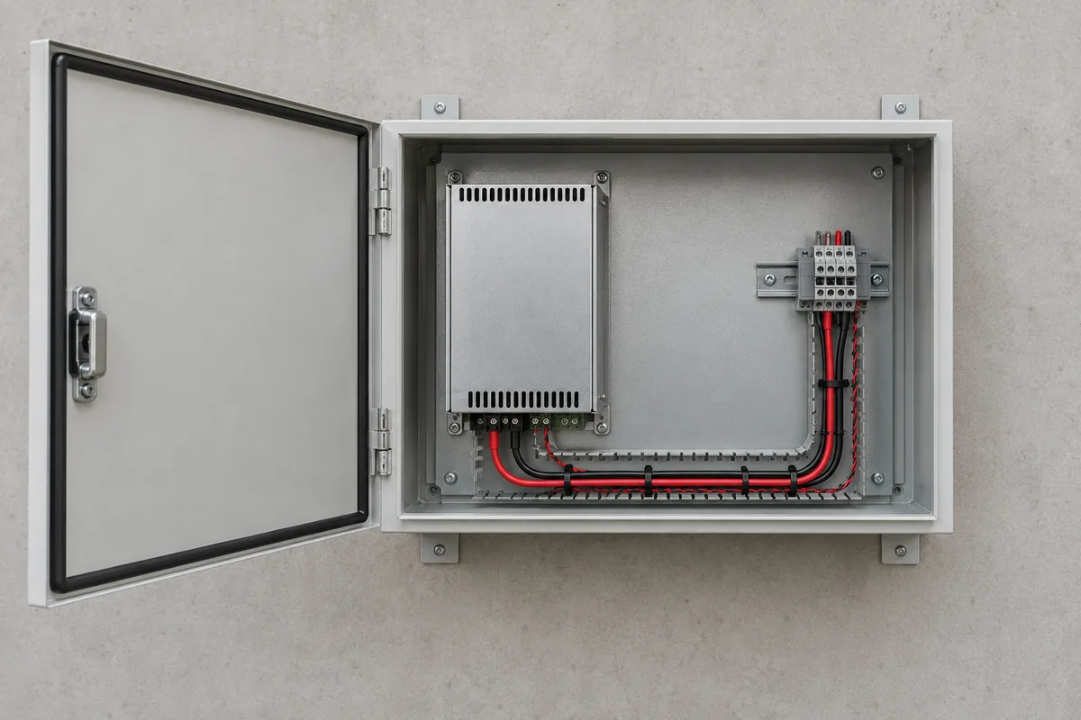
The model offers a 12 V auxiliary output rated at 0.8 A, a remote ON-OFF input, DC_OK, and a temperature alarm. The auxiliary rail is not another 48 V power channel. In the documented remote-switch behavior, closing the control switch disables the main output while the 12 V auxiliary output remains unaffected; opening it allows the main rail to establish. This can let a cabinet controller remain powered while the high-power rail is intentionally off. It also means “12 V present” does not prove that the main 48 V output is available.
DC_OK is a low-current status output, with the datasheet specifying a maximum output-current capability of 1 mA and maximum external voltage of 5.5 V. Its high state indicates the main output has established; low indicates that the main output is off. The temperature alarm is a separate signal describing internal temperature state. Neither output should be used as a load-driving supply. A controller input must respect the stated electrical limits and the auxiliary-ground reference defined in the connector documentation.
The front indicator has three documented states: green for normal main-output operation, red for a protection state, and blinking red for standby when input and PFC are normal but remote ON-OFF has not enabled the main output. The indicator relates to the main rail, not the auxiliary rail. A blinking standby indication suggests a different investigation from a protection indication. Measure voltage at the output terminals and load.
Great Wall lists RS-485-capable DA and DB contacts for monitoring or current-sharing communication, while describing upper-computer monitoring as customizable. This does not establish a telemetry map or PMBus compatibility. Request the communications protocol for the exact hardware and firmware revision.
Parallel sharing has a quantified ceiling
The GSP1600W datasheet explicitly permits up to four units in parallel with built-in active current sharing. It also gives installation rules that make this more than a multiplication of nameplates. Parallel output wires should be equal, short, and thick, with length no more than 30 cm before the common junction. Unit output-voltage settings should differ by less than 0.2 V. The DA, DB, and ground communication wiring is specified as twisted to limit interference. A system layout that ignores these details has not met the manufacturer’s stated sharing conditions.
Great Wall’s allowable total output-current formula is each unit’s rated current multiplied by the number of units and by 0.9. For two 48 V units, that gives 33.5 A × 2 × 0.9 = 60.3 A. At a nominal 48 V, this corresponds arithmetically to about 2.89 kW, subject to the set point, input, temperature, and other operating limits. Four units yield 120.6 A by the same formula, not 134 A. The 0.9 factor is in the manufacturer guidance and should not be silently replaced with the summed nameplate current.
The datasheet also warns that sharing may be imperfect below 5% of the units’ combined rated current. A lightly loaded cabinet may therefore show unequal unit currents without contradicting the published behavior. At high load, conductor resistance, connection quality, and set-point matching become more consequential. Parallel capacity does not automatically establish redundancy: if a cabinet must survive one failed unit, compare its required load with the permitted capacity of the remaining units under the same 0.9 sharing rule and site derating, then account for fault isolation and the load’s transfer tolerance.
Parallel capability does not imply live insertion. Removing this fixed, bolted supply may require isolation of both input and output wiring. Any continuous-maintenance function must come from the cabinet design.
Cabinet heat and fault behavior around the 41 mm enclosure
The thin 41 mm height can make the model attractive where cabinet space is limited, but its fan inlet, exhaust, terminal access, mounting, and cable bend radius consume additional space beyond the metal dimensions. Great Wall’s −25°C to +70°C operating range is accompanied by an output derating curve. A +70°C ambient claim is therefore not equivalent to a full 1600 W claim at +70°C. The actual air temperature at the supply inlet, rather than room ambient, is the relevant starting point in a cabinet with other heat sources.
At the published 92% full-load efficiency, a simple calculation gives approximately 1.74 kW of AC input for 1600 W DC output and about 139 W of conversion loss. That estimate is tied to the cited full-load efficiency condition. It is useful for understanding the scale of heat that cabinet ventilation must remove, not a measured heat output under every line and load condition. Fan-speed control can change noise and airflow as internal temperature changes, so a blocked intake or recirculated exhaust needs to be avoided in the physical layout.
The protection section lists overvoltage, overcurrent, overtemperature, and short-circuit behavior. It states that overtemperature can recover automatically after the abnormal condition is removed, while a short circuit latches and requires a power cycle to recover output. A cabinet controller should distinguish these cases rather than repeatedly toggling remote ON-OFF as a universal reset. The documented overvoltage threshold for the 48 V model is relative to the set output voltage, with a stated upper bound below 60 V. That is another reason to assess the connected load’s maximum voltage rather than assuming “48 V equipment” tolerates any transient below 60 V.
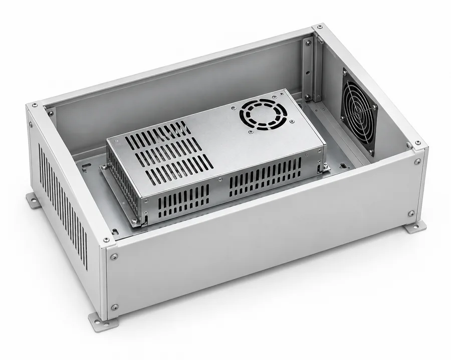
GW-GSP1600W-48 fits an application that can mount and cool an enclosed supply, provide a compatible AC or high-voltage DC source, and use a 48 V rail within documented load limits. Its practical differentiation is not simply 1600 W in a small box: remote-sense placement, PV-to-VR fallback, distinct status signals, and the manufacturer’s 0.9 parallel-current rule each change how a controlled cabinet should be designed. Those details make the exact datasheet and the receiving system’s electrical drawing the right pair of documents for evaluating this model.