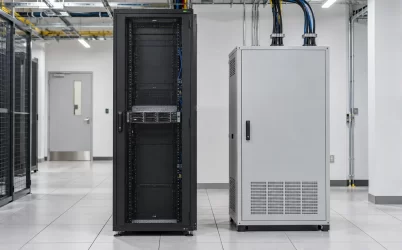
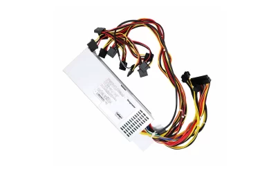
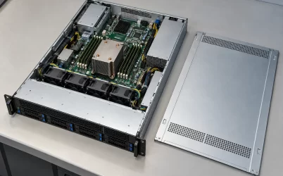
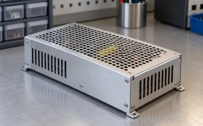
Server power supply applications are not just different workloads attached to the same box. An enterprise rack server may carry its own removable AC-to-DC modules. A shared compute chassis can power several nodes from one common frame. A storage enclosure may reserve capacity for drives and controllers, while an accelerator rack may move conversion into a separate power shelf. At a telecom edge site, the available source might be DC rather than the AC feed expected by a data-center server. These arrangements use similar conversion principles, but they place the electrical and service boundaries in different places. The useful question is therefore not simply “Where are server PSUs used?” It is “What equipment does this particular PSU actually power, and where does that power path begin and end?”
The application changes where conversion happens
In a conventional rack server, the power supply receives the site’s supported input and delivers a regulated output into that server’s internal distribution board. Board-level converters then feed processors, memory and other loads. The PSU normally does not power a neighboring network switch, a rack cooling unit or the room’s monitoring system. Those devices may have their own supplies even though they share the facility feed. Calling all of them “server power” obscures the component a replacement buyer actually needs.
Other applications move the boundary. A multi-node enclosure can distribute power from a shared set of frame PSUs to several compute sleds. A rack power shelf can feed a busbar, leaving each tray to perform its downstream conversion. A DC-input server module can accept a site battery-backed distribution feed where an AC-input module would be unsuitable. These are different hardware locations, not merely different wattage choices. That distinction explains why an application label on a product listing is useful context but cannot establish interchangeability.
| Application arrangement | Where the main supply sits | What changes in the power question |
|---|---|---|
| Individual enterprise or cloud host | Inside one server chassis | One server’s bay, distribution board and service state define the match |
| Shared compute frame | In the common enclosure | Multiple sleds and frame devices draw from one managed pool |
| Storage enclosure | In the controller or drive enclosure | Controllers, media and spin-up or service states share the available output |
| DC-fed edge server | In the server, downstream of a site DC feed | Input source, polarity and installation rules differ from an AC rack |
| Rack-bus compute | In a separate power shelf | A rack bus and tray input replace the usual per-server AC inlet |
The rows are architecture patterns, not a claim that every system in an industry follows one design. Cloud services may run on ordinary two-socket rack servers, shared frames or rack-bus equipment. An edge deployment may use an AC wall feed or a DC plant. The installed chassis and electrical drawing settle which pattern applies.
One rack server gives each host its own service boundary
The familiar enterprise-server application puts one or more PSU cartridges in each host. The operator can identify a failed server, check that its remaining power path can carry the active load, and replace a supported module at that chassis. This arrangement makes the server a convenient unit of maintenance. It does not make all removable modules interchangeable: the mechanical guide, blind-mate contacts, output arrangement, control signals, firmware expectations and airflow direction remain platform-specific.
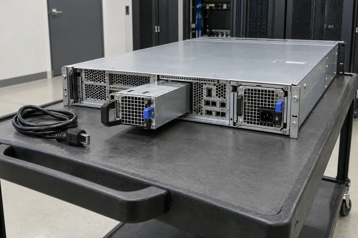
Cloud and virtualization clusters often contain large numbers of such hosts. Their workload software may move or restart services on another machine after a failure, but software resilience does not change the electrical requirements of the failed host. Conversely, a host with two PSUs is not automatically protected from a facility feed fault if both inlets terminate in the same upstream failure domain. The application changes the operator’s availability strategy, while the chassis still determines the physical spare.
For a fleet, the most useful application-level question is whether the server itself must stay up through a module failure or whether the service can tolerate losing one node. The answer affects how many working modules and upstream feeds are required at that host. It does not authorize mixing PSU families. A documented chassis option may support a different output rating from another approved option, yet that substitution still depends on its specified PDB, input conditions and firmware policy. Treat the server’s supported bill of materials as the boundary of the replacement search.
Powernexu’s Greatwall server power supply category illustrates the range of module families a buyer may encounter. It is a product catalogue, not a compatibility list for every rack server.
A shared chassis makes power a frame-level resource
A blade or composable frame reverses the per-host assumption. Several compute modules can rely on supplies installed in the enclosure rather than carrying independent AC-input cartridges. The frame may also power fans, management hardware, interconnects and storage options. If a supply drops out, the surviving set must serve the entire installed frame load, not merely one compute sled. Capacity planning therefore starts with the actual population and the enclosure’s supported power configuration.
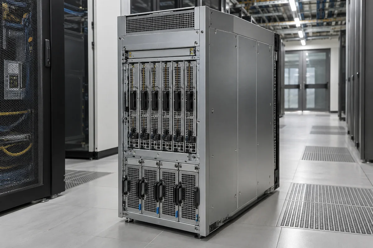
The frame’s power-distribution board is a common point in this design. A PSU can be mechanically removable, yet the power path beyond it is shared. Removing a sled may reduce load; adding an interconnect or a second sled can consume capacity that a simple count of processor modules would miss. A frame can also implement power policies or redundancy modes that change the usable output after one module fails. Those modes are defined by the platform, not by a generic phrase such as “N+1 capable.”
This is why a shared-chassis spare should be searched under its enclosure identity. A visually similar module from a stand-alone server might carry the same apparent output rating while using a different contact pattern or management interface. Even within one enclosure family, a power-supply option may depend on a particular input voltage, cable set or installed module population. A useful application description names the frame and which devices it powers. “Server power supply for blades” is too broad to approve a replacement.
Storage arrays and accelerator servers load the path differently
Storage applications often make continuous access and orderly service more important than a processor’s short peak alone. A storage enclosure can contain controllers, many drives, fans and expansion hardware. An individual server that hosts storage software is a different object from a dedicated drive shelf; the two may use different PSU mechanics and distribution schemes. In either case, the load to consider is the specific enclosure’s complete operating state. A drive population change or additional expansion shelf should not be folded into a vague “storage PSU” rating without identifying which supply powers it.
High-density accelerator servers create another type of application pressure. The electrical path may serve multiple GPUs, processors, memory, networking and a dense fan system. Sustained load and rapid changes can have different effects on the PSU, downstream distribution and cooling arrangement. A nominal module wattage alone says little about how the platform distributes output among accelerator zones or what happens when one module or feed is removed. The host manufacturer may impose power caps or workload throttling under reduced capacity; that behavior cannot be inferred from the PSU’s label.
For the accelerator case, the distinction between server output and connector-level delivery becomes especially visible. A PSU that can deliver adequate aggregate DC output still needs a supported PDB and conductors to bring it to the actual loads. Heat generated by conversion must leave the chassis under the installed airflow direction. Those concerns are not special because the workload has an AI label; they become prominent because power density and the consequence of a weak downstream path are greater in that particular platform. The application tells the designer where to look, not which model will automatically fit.
Edge and telecom sites make the input source part of the application
An edge server may live in a compact shelter, a telecom room, an industrial cabinet or a small remote rack. Such sites can have different power sources and maintenance access from a central data center. Some equipment accepts conventional AC. Other systems are designed around a DC plant. A label that merely says “server PSU” does not reveal which one. The input type and supported range must come from the actual module and site design, not from the fact that the equipment runs a server workload.
At a battery-backed telecom site, a negative nominal 48 V distribution system is one possible source. A compatible DC-input server module can convert that feed into the output required by its host. That does not make a 48 V output supply, or an AC-input module whose title includes “48 V,” an acceptable substitute. The conductors, polarity convention, protective devices and mating interfaces belong to the installed DC power system. A site engineer may also have to account for the full battery/distribution voltage range rather than a single nominal value.
The remote application shifts the practical service question. If the site has no on-site technician, detecting a failed module and continuing with the remaining source can matter as much as a quick cartridge swap. In a compact cabinet, cable bend, air intake and extraction clearance may constrain a physically compatible module. Environmental limits must be read from the specific equipment documentation; an outdoor enclosure or telecom use case on a marketing page does not prove that a bare PSU tolerates the site’s actual heat, dust or humidity.
Powernexu lists the CRPS550N2 as a 550 W, 12 V CRPS option for compact infrastructure and edge-related applications. That is an example of application positioning, not evidence that it will mate with an arbitrary edge server. The host bay and input option still determine whether it belongs on a real bill of materials. The distinction between a supported application and a verified replacement matters most when a remote site cannot afford a wasted service visit.
Rack power shelves are a different answer to dense compute
Some large compute installations move rectification out of individual server chassis. A power shelf converts incoming power and supplies a DC rack bus; server trays draw from that bus and perform the conversion they need downstream. This arrangement can change the rack’s service points, copper distribution and redundancy design. It also changes the meaning of “server power supply”: the replaceable converter may be in the shelf, while the tray has a DC input stage rather than a familiar rear AC PSU bay.
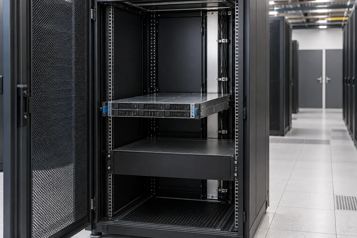
The Open Compute Project’s Open Rack V3 power-shelf specification describes one defined rack-bus implementation. It is a useful primary example precisely because it documents a particular architecture; it does not mean every AI rack or every high-power server uses that bus. A conventional rack with high-wattage AC-input modules remains a different design. The application is “dense compute,” but the conversion boundary is decided by the rack architecture.
For a shelf-fed tray, the rack bus and tray mating interface become part of the power supply application. An otherwise capable converter is not a drop-in replacement if it does not belong to the supported shelf, bus voltage or rack control scheme. Upstream feed loss and shelf-module loss may be separate events with separate redundancy provisions. Moving conversion to a shared shelf can simplify one part of the tray while increasing the importance of the common rack distribution path. That trade-off should be described at the architecture level rather than reduced to a claim that rack power is inherently more reliable or efficient.
When comparing server power supply applications, describe that boundary in a sentence: the available source, the converter’s location, its immediate load, and the level at which a module can be replaced. This is not a request to collect paperwork for its own sake. It prevents a genuine category error, such as buying a host PSU for a shared frame or an AC module for a DC-fed site. It also keeps a broader application article from pretending that one module family is suitable for all enterprise, storage, edge and accelerator systems.