Server PSU hold-up time is the interval during which a power supply keeps a specified DC output within its required limits after AC input disappears. It is a short ride-through property, not battery backup. The useful question is not simply “how many milliseconds?” A server has a main power rail, often a separate standby rail, a power-good indication, and a host that may respond to an input-loss warning. Those elements need not have the same time limit. A brief AC interruption may be invisible to the workload, may trigger throttling without shutdown, or may outlast the PSU’s stored energy and force a restart. The outcome depends on the exact PSU and platform, the load at that moment, the input condition, and how quickly the upstream source returns.
The AC input disappears before the DC output does
An AC-input server PSU first converts incoming power into an internal energy reservoir and then regulates its output. When the input vanishes, energy already stored inside the converter can briefly sustain the DC bus. The output does not have to collapse at the same instant the AC waveform goes away. Yet the reservoir is finite. Once the PSU can no longer regulate its specified output, the host cannot assume the rail remains usable merely because a fan is still coasting or an indicator is still lit.
Think in terms of an event sequence rather than one number. AC loss begins at an inlet. The converter detects or rides through the input change. Its main output remains in regulation for some interval under the stated load. A power-good or equivalent status signal changes according to the platform design, and the host may have a chance to reduce consumption before the rail leaves its allowed range. If AC returns soon enough, the server may continue. If it returns after the relevant boundary, the PSU may restart under its normal startup requirements while the host has already reset. A claim of “survives 12 ms” says little unless it states which output was watched and what counted as survival.
The waveform of the interruption matters. A complete drop to zero, a partial sag, and a missing half-cycle are different inputs. A sag may allow some energy to continue entering the converter; a zero-voltage dropout does not. A published test may begin the disturbance at a defined phase of the AC cycle, or exercise multiple phases because the stored energy at interruption can differ. Such details belong to the model-specific test method. They should not be silently replaced by a generic UPS transfer-time figure.
Main output and standby output may have different clocks
Many server architectures maintain a standby supply for management functions even when the main output is off. During a running-host AC loss, the main and standby paths can have different loads, storage allocations, and regulation requirements. Their hold-up times therefore need not match. A management controller remaining alive for an instant after the main rail has fallen does not mean the processors are still executing. Conversely, a main-output hold-up figure cannot be assumed to cover a standby rail under its own maximum load.
Intel’s R2000GZ/GL technical product specification makes this distinction concrete for that particular server family. It states a 12 ms AC-line hold-up at 70% load and separately calls for the 12V standby output to remain regulated for at least 70 ms at full standby load during an AC dropout. These are requirements in an older Intel platform specification, not universal values for modern CRPS modules or every server. The larger standby number cannot be used to claim that the main compute load survives a 70 ms mains interruption.
Power-good timing introduces another boundary. It can signal that a rail is no longer guaranteed before the output has reached zero, allowing host logic to react in an orderly way. The meaning and timing of that signal depend on the PSU and board interface. A management event recorded after power returns may not resolve the exact millisecond at which the main rail left tolerance. Do not infer hold-up from the persistence of an LED or from a BMC log timestamp alone; these observations have their own sampling and reporting delays.
Load changes the amount of time available
Stored energy must support the actual output demand during the interruption. More output power generally consumes the available energy faster, all else equal. A PSU tested at 70% load does not necessarily meet the same hold-up duration at 100% load. At a low idle load it might sustain regulation longer, but that is not a substitute for the published operating guarantee. The converter’s control behavior, internal bus limits, efficiency, input-voltage history, temperature, and aging all affect the exact result.
A simple energy calculation shows why load cannot be omitted. If a hypothetical server draws 800 W of DC power, sustaining that demand for 12 ms requires at least 9.6 joules delivered to the load. The PSU would need more stored energy because conversion is not lossless and because not all energy in its reservoir is usable before regulation fails. This calculation is illustrative, not a capacitor-sizing instruction or a claim about a Powernexu model. Halving the load changes the energy required for the same time, but it does not justify assuming twice the hold-up time: the converter may reach an internal voltage or control limit first.
Server load also changes during the event. A CPU or accelerator can be drawing far more than its average power when input disappears. Some platforms detect AC loss early and throttle to extend operation; others do not expose such a policy. Intel describes Smart Ride Through throttling for the R2000GZ/GL family, tied to heavy-load AC dropout behavior. That is a specific platform feature, not something to assume from the PSU wattage label. If the host lowers its load quickly enough, the electrical demand during the remaining milliseconds changes. Whether that preserves the workload depends on the complete server response, not only the converter’s bench hold-up result.
A UPS transfer is not just a race between two labels
A standby or line-interactive UPS may take a finite time to change source during an outage. It is tempting to compare the UPS’s advertised transfer time with the PSU’s advertised hold-up time and declare the pairing safe if one number is smaller. That comparison is incomplete. The UPS transfer specification may be a typical rather than a worst-case value, and its output can sag or change shape during the transition. The PSU hold-up figure may apply at a particular input voltage and output load. The server may simultaneously change power demand or react to an input-loss signal.
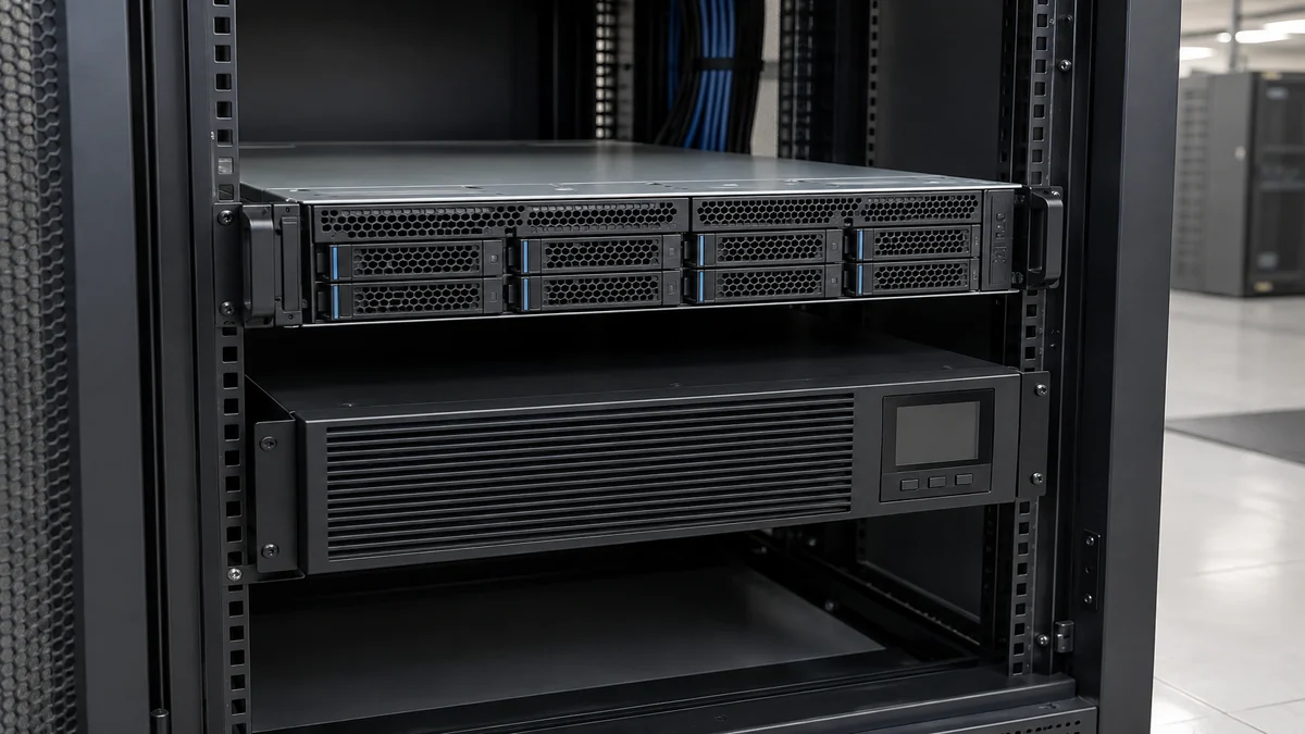
There is also a return-to-power event. If the PSU’s internal bus falls far enough, restored input can produce inrush as the reservoir recharges. The UPS inverter must tolerate that demand along with other loads on the same output. A nominal transfer shorter than the PSU’s hold-up interval does not prove that the UPS voltage remains acceptable throughout the transition or that the return transient is harmless. This interaction is one reason to evaluate the actual equipment combination rather than quote a single millisecond threshold.
The boundaries are different for a double-conversion UPS, whose output architecture can avoid a source-transfer interruption at its load terminals under normal operating conditions. That does not eliminate all upstream, battery, overload, maintenance, or configuration risks. The UPS’s purpose is to provide stored external energy for a defined load and duration. The PSU’s internal hold-up bridges a much shorter interruption at its input. Neither redundancy nor a UPS turns an undocumented hold-up figure into a guaranteed server outcome.
Two PSUs can experience one dropout or two
In a redundant server, each PSU may receive an independent AC feed. If only one inlet loses AC, the remaining module may continue supplying the host through the platform’s power-distribution arrangement. In that case, the continuity question is whether the surviving PSU and shared path can carry the failed-state load, not simply how long the affected module holds up. If both inlets share the same upstream PDU, circuit, or UPS event, both modules may start consuming their stored energy at nearly the same time. Two cartridges do not add their individual hold-up durations in series.
Load sharing complicates the event. In a pair that normally shares power, loss of one input can shift demand to the survivor. Its input may remain valid, but its output, thermal and current limits still matter. A second module kept in a cold or low-load state may need to change operating state according to host policy. The platform’s response to one module’s AC-loss warning can matter before either output collapses. For these reasons, a redundant PSU rating and a hold-up rating solve related but distinct questions: one concerns a source or module disappearing while another remains, and the other concerns how a particular module responds during a temporary input interruption.
What a test result must say to be useful
A meaningful hold-up result identifies the exact PSU or complete server, input voltage and frequency, output load, measured rail, temperature if relevant, dropout shape and timing, and pass criterion. The criterion might require the main output to remain inside its regulation band throughout the disturbance. Another test might only require no permanent damage and successful restart. Those are radically different outcomes for a running workload. A specification should state whether the test is for one module alone, a populated redundant chassis, or a host with throttling enabled.
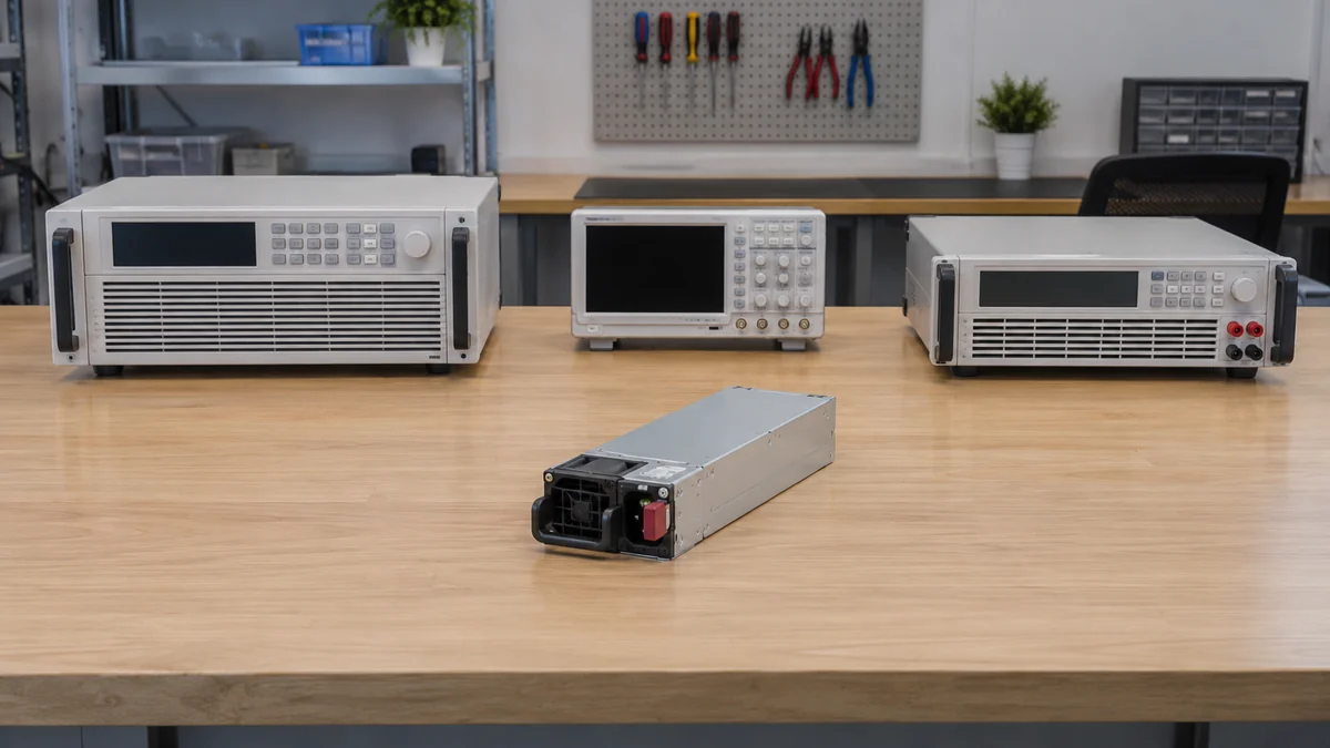
Capturing fast electrical behavior requires suitable isolated instrumentation and a controlled test setup. It is not an instruction to probe a live server PSU or defeat its enclosure. Authorized laboratory personnel can correlate AC input, main DC output at the supported measurement point, standby rail, power-good state, and host response without relying on a human watching LEDs. The time bases of the measurements have to agree; a UPS event log with one-second resolution cannot establish a ten-millisecond hold-up boundary. A production environment may use vendor documentation and approved system testing instead of intrusive measurement.
A short dropout may still be a real incident
Suppose a site observes a brief upstream AC disturbance and the server stays running. That does not by itself tell whether its PSU hold-up bridged the whole event, a UPS supplied acceptable power, one redundant inlet remained live, or the host reduced demand. Several mechanisms may have contributed. If the server resets, the opposite shortcut is equally unsafe: the cause may be an excessive transfer interval, a UPS overload, a simultaneous loss of both feeds, insufficient failed-state PSU capacity, or a server-side power policy. The same visible outcome does not identify the failed boundary.
A useful incident record aligns events by time and source: the upstream disturbance, UPS operating state, each PSU’s input-loss report, host power-management response, and whether workload execution continued. This is not a universal troubleshooting checklist. It is the minimum chronology needed to avoid attributing a multi-component transition to one published millisecond figure. If evidence is too coarse to establish the sequence, say so. Replacing a PSU solely because the rack rebooted during a power event could leave the actual source, UPS interaction, or distribution constraint untouched.
Hold-up time answers a narrow but important question: for the exact conditions in its specification, how long does a defined DC output remain valid after AC input drops away? It does not answer how long the server can run on battery, whether dual feeds are independent, or whether a host will avoid a reset in every possible outage. A server can benefit from hold-up only when the upstream disturbance, PSU load, other power path, and host response all fit within their own boundaries. The millisecond number becomes useful once those boundaries are named.