A 480Y/277V data-center service does not specify how a server receives DC power. One architecture distributes 277V AC from phase to neutral through a suitable rack PDU to individual, explicitly compatible server PSUs. Another can feed a rack power shelf through a documented three-phase configuration, such as the cited system’s nominal 400/230V, 415/240V, or 480/277V AC options and distribute regulated DC to IT equipment. The difference is where AC-DC conversion lives: inside each server or in shared rack infrastructure. That choice changes the power path, fault boundary, service model, and equipment that can be connected. Neither the presence of a 480V facility feed nor a PSU’s broad input-range label establishes compatibility by itself.
One facility voltage label, two different electrical paths
In a 480Y/277V wye system, nominal 480V is measured between phases and nominal 277V between one phase and neutral. A three-phase rack feed and a single-phase PSU inlet therefore do not see the same voltage even when both originate from the same distribution system. The notation is not interchangeable with a generic “480V server PSU.” The latter phrase can incorrectly suggest that an individual hot-plug module receives 480V across its input contacts.
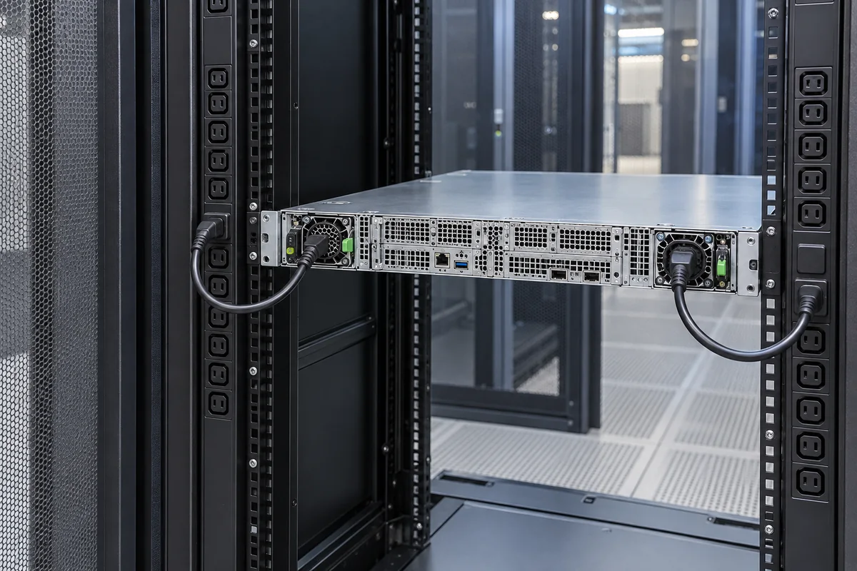
The direct-PSU path is facility distribution to a rack PDU, then a correctly rated 277V outlet and cord, then the AC-DC converter inside a supported server. Each server retains its own conversion and typically distributes the resulting low-voltage DC within its chassis. The alternative shelf path sends a documented three-phase feed to a rack-level converter. The shelf supplies a defined DC bus to equipment designed for that bus, often through rack busbars or a distribution assembly. The servers in that arrangement may not contain the conventional AC-input module at all.
Those are architecture descriptions, not wiring instructions. Protective devices, earthing, conductor and connector ratings, neutral treatment, branch design, and permitted service work belong to the facility’s electrical design and applicable rules. The immediate server-power question is simpler: what electrical waveform and voltage actually reach the next piece of equipment? A drawing that labels only the building service leaves that answer unresolved.
With direct 277V delivery, every server owns its converter
Direct 277V delivery is attractive when the selected server family offers an approved PSU option for that input and the facility can deliver the matching outlet and cord system. The rack PDU apportions the incoming three-phase system into appropriate single-phase outlets. Each PSU then converts its own AC input into the DC rails expected by its host. A server with redundant modules can retain the familiar per-chassis service boundary: one module may be replaced under the host’s supported procedure while the other continues supplying the permitted load.
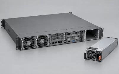
That service model does not follow from the number 277. It follows from the exact server and power assembly. The OEM must support the selected PSU variant, mating connector, airflow, firmware behavior, available output at the intended input, and redundancy configuration. An input range extending above nominal 277V may be a useful preliminary clue, but it is not evidence that the PSU is approved for a particular host or that the entire rack feed is suitable. Even a mechanically identical module can differ in electrical input and platform support.
A practical upside of per-server conversion is a familiar ownership boundary. Operators can attribute a converter fault to a server bay, use the host’s diagnostics, and replace only that module when the platform permits. The rack does not need one common DC bus shared by all attached servers. Conversely, every chassis retains power-conversion hardware, its associated heat path, and a set of AC inlets and cords. At scale, the result is a large population of independently managed converters rather than a smaller number of rack power shelves.
Power from the two rack feeds should also be described honestly. Two server cords connected to separate PDUs can protect against loss of a module or one feed only when the complete upstream paths and the surviving module capacity support that claim. If both cords ultimately share a transformer, switchgear section, or maintenance domain, the apparent A/B arrangement may retain a common failure point. The voltage is not the source of redundancy; the topology and available capacity are.
A three-phase shelf moves conversion outside the chassis
A rack-level power shelf accepts a specified AC feed and creates a shared DC output for compatible equipment. One documented example is the Vertiv PowerDirect Rack system in its official application guide. It lists nominal three-phase 400/230V AC through 480/277V AC inputs and a 50V DC output. The paired AC values distinguish three-phase line-to-line voltage from phase-to-neutral voltage; they do not describe a 480V single-phase server inlet. These are particulars of one system, not universal requirements for Open Compute racks, power shelves, or Powernexu products.
The visual power path changes substantially. Instead of individual AC cords terminating at a converter in each server, a three-phase feed terminates at the shelf; a regulated DC bus continues from the shelf to IT equipment. The rack becomes an active part of the power system. Its busbar or cable interface, protective strategy, shelf controller, monitoring, and service clearances matter as much as the AC source. An ordinary AC-input server cannot be made into DC-bus equipment by replacing its power cord.
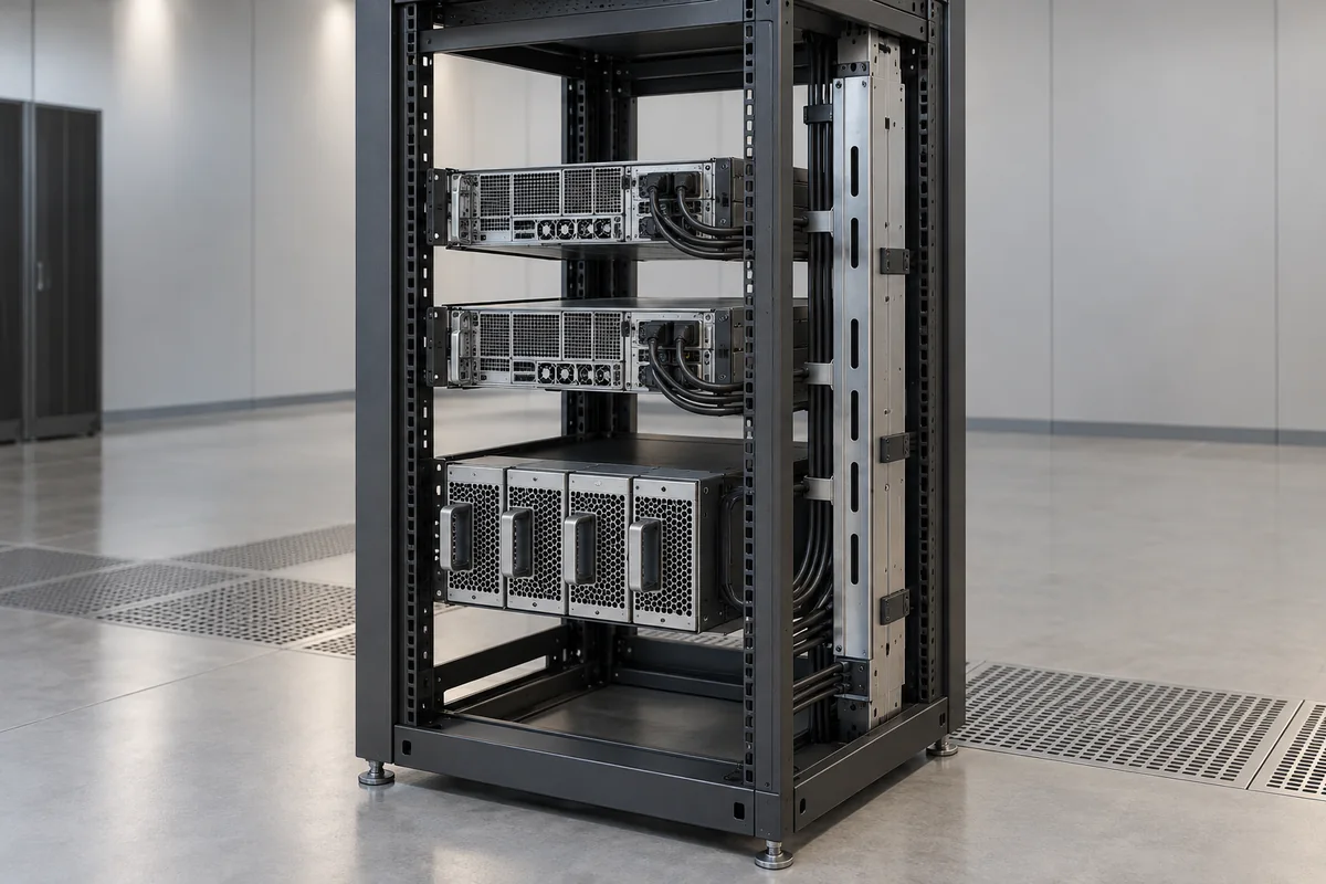
Moving conversion upstream may simplify a purpose-designed IT chassis. It can free space previously occupied by individual AC-DC modules and can place power conversion and battery integration at rack level when the chosen architecture supports those functions. It also creates a shared assembly whose faults can affect several loads. Shelf modules, busbar distribution, and protection therefore have to be engineered as a coordinated system. A common bus is not a shortcut around branch protection or the failure consequences of a short at one attached load.
Not every rack shelf takes 480V three-phase input. The cited Vertiv PSS5033 system also lists a single-phase 200–277V AC operating range while distributing DC at rack level. That is an important counterexample: “rack-level conversion” describes location and sharing, whereas “three-phase 480V input” describes one possible source interface. The two design choices should not be collapsed into a single standard. The exact shelf specification controls the required feed, output bus, allowable module population, redundancy behavior, and IT connector.
For a mixed fleet, rack-level DC distribution can be an obstacle rather than an advantage. Conventional servers with supported AC PSUs may coexist with networking devices or storage systems that expect different inputs. A dedicated DC-bus rack is easiest to justify when the compute equipment is designed around that bus from the start. An adapter or extra conversion stage can bring unlike loads into the rack, but it changes the loss, cost, protection, and maintenance calculation that motivated centralized conversion.
Where loss and heat actually move
It is tempting to declare either architecture more efficient based solely on the higher AC voltage or the number of converters. Neither shortcut establishes the result. Distribution losses depend on current, conductor resistance, run length, phase balance, and the actual arrangement of transformers, UPS equipment, PDUs, cords, and contacts. Converter losses depend on the exact PSU or shelf module and its operating load. A rack-level shelf does not eliminate AC-DC conversion; it relocates it.
Consider the same IT load supplied through two feasible designs. In the direct arrangement, the loss chain may include facility distribution, a 277V rack PDU and cords, then many per-server converters. In the shelf arrangement, the chain may include the three-phase feed, shelf modules, a shared DC bus, and any server-side DC-DC conversion that the equipment requires. If one design removes a transformer stage, that stage’s actual loss can be credited only if it is absent from that particular facility topology. If another design adds a DC conversion stage, include its measured or documented operating-point loss rather than treating the shelf output as usable processor power.
Higher voltage generally reduces current for comparable delivered power in a comparable circuit, which can reduce resistive loss. But comparing a 277V single-phase branch with a 480V three-phase shelf feeder by dividing watts by voltage alone is misleading. The phase arrangement, power factor, duty cycle, and current per conductor differ. The more useful comparison holds the delivered IT workload constant, maps every conversion and distribution boundary, and evaluates loss at realistic operating points. Exact energy savings require actual equipment data; there is no universal percentage attached to the words “277V” or “480V.”
Heat also changes location. Per-server AC-DC loss is removed through each server’s cooling path. Shelf-conversion loss concentrates around the rack power shelf and its air or liquid cooling interface, while downstream DC-DC loss remains near the IT loads. That shift can help a designed rack, yet it can also create a local thermal burden. The cooling system must account for where power is dissipated, not simply for the total facility electrical input.
Measurements must follow the same boundary. Input energy at the facility panel, output energy from a rack shelf, and DC delivered to a server board are not interchangeable meter readings. A shelf may expose one useful aggregate number while a per-server design exposes individual PSU telemetry. Neither measurement is automatically the billed energy or the power consumed by processors. When comparing alternatives, identify the measurement point before calling one architecture more efficient.
Faults expose the real redundancy boundary
The two architectures fail in different places. With per-server PSUs, a failed module can remain local to one chassis if its partner and the upstream feed can carry the permitted server load. Shared facility faults still reach every affected rack. With a shelf, a failed converter module may be absorbed by spare shelf capacity, but a busbar fault, shelf-controller problem, or common AC feed can span multiple IT devices. Redundancy has to be drawn around the shared infrastructure, not inferred from the count of hot-swappable modules.
Suppose a rack shelf has several conversion modules and advertises N+1 operation. The statement is meaningful only relative to the defined rack load and the failure of one specified module. It does not by itself cover a bus short, an upstream breaker trip, or simultaneous maintenance on shared distribution. Likewise, a server with two 277V PSUs is not automatically protected from loss of a single common rack PDU. The architecture must show which component can fail, what remains energized, and how much power the surviving path can deliver without violating its ratings.
Service work follows the power boundary. Replacing an approved server PSU affects one host and its bay. Replacing a shelf converter can be live work under a supported shelf design, but the operator may be handling infrastructure that serves many systems. Busbar, DC branch, and input-feed maintenance can have a much wider blast radius than a module swap. The operational advantage of centralized conversion should therefore be evaluated alongside the consequences of common equipment maintenance, not only its possible space savings.
Two schematic lines can prevent an expensive category error
For a direct 277V design, the decisive schematic line is: 480Y/277V distribution → rated rack outlet and cord carrying 277V phase-to-neutral → approved AC-input server PSU → the host’s DC distribution. For the cited shelf example, it is: the documented three-phase rack feed → compatible power shelf → regulated 50V DC bus → IT gear designed for that bus. Both start with high-voltage facility power. They differ at the inlet, converter, distribution medium, and server interface.
That difference is why a facility plan should name the conversion location before naming a PSU family. If the fleet consists of conventional servers offering supported 277V modules, direct AC delivery preserves their familiar electrical and service interfaces. If a new rack platform is designed around a common DC bus, a compatible power shelf can make conversion a rack-level function. A mixed fleet may require separate power zones rather than one compromise rack. None of these conclusions approves a particular module or wiring arrangement without the exact equipment documentation.