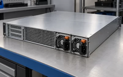
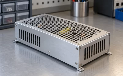
GW-PA1600I is a Great Wall Hot Swap supply listed at 1600 W, with a 12 V/133.4 A main output and a separate 5 Vsb/2 A standby output. Its published input windows are 90–290 Vac and 192–288 Vdc. Those figures describe a particular two-rail power source, not a generic 1600 W server spare. The practical question is how the host distributes more than 130 A at 12 V while keeping its management circuits alive on standby power. A buyer also needs the controlled interface drawing before treating a matching wattage, voltage, or hot-swap label as proof of interchangeability.
The model sits in Great Wall’s Hot Swap group
Great Wall’s Hot Swap catalog names GW-PA1600I and lists 1600 W, 12 V/133.4 A, 5 Vsb/2 A, 90–290 Vac, 192–288 Vdc, and CCC. The Powernexu GW-PA1600I product page carries the same headline ratings. This agreement is useful for identifying the model and its electrical class. Detailed operating limits and interface requirements still need an exact-model datasheet; the public catalog does not disclose the mating connector, contact assignment, mechanical drawing, efficiency curve, output tolerances, protection thresholds, or current-sharing behavior.
Hot Swap describes a product group. It does not certify that any server will tolerate live removal. Such operation requires a host designed for the exact interface, alternate capacity when continuity is required, and control of insertion and output connection. A 12 V output does not make this a standard CRPS part. A similar power bay may use a different connector, latch, depth, airflow orientation, or management protocol.
The manufacturer’s nearby GW-PA2700I and GW-PAH3000I-F entries illustrate why the family name is a weak compatibility guide. The former is listed at 2700 W and 54 V; the latter at 3000 W and 53.5 V. GW-PA1600I instead serves a high-current 12 V architecture with an explicit 5 V standby rail. A backplane intended for a 54 V bus cannot be inferred to accept the 12 V model, even if both units use the words Hot Swap.
The 12 V rail creates a high-current distribution problem
The published 12 V and 133.4 A entries multiply to approximately 1600.8 W; rounding explains the small difference from the 1600 W headline. That arithmetic places the module in a different distribution regime from a similarly rated 48 V or 54 V source. For a fixed output power, lower voltage requires more current. The conductors, board copper, mating contacts, return path, and branch protective devices have to be appropriate for the actual current they carry. A connector that looks substantial in a photo is not a current-rating document.
At 133.4 A, a hypothetical 2 milliohm resistance in an aggregate output path would drop about 0.267 V and dissipate roughly 35.6 W. These are illustrative circuit calculations, not measurements of GW-PA1600I or any Powernexu product. Their value is in showing the scale: small resistances become large local heat sources at this current. If the resistance is concentrated in one loose contact, the thermal problem is more severe locally than an evenly distributed calculation suggests. Conversely, several parallel contacts can share current only when their geometry and connection quality support the intended distribution.
The 12 V rail commonly feeds a distribution board before local converters generate the lower voltages used by processors, memory, storage, and control electronics. That is an architecture example, not a published GW-PA1600I reference design. The path from the module to each converter should be represented as a circuit with both supply and return conductors. An attractive busbar arrangement can still fail to deliver enough voltage at a remote load if its return path or branch contact carries excessive resistance.
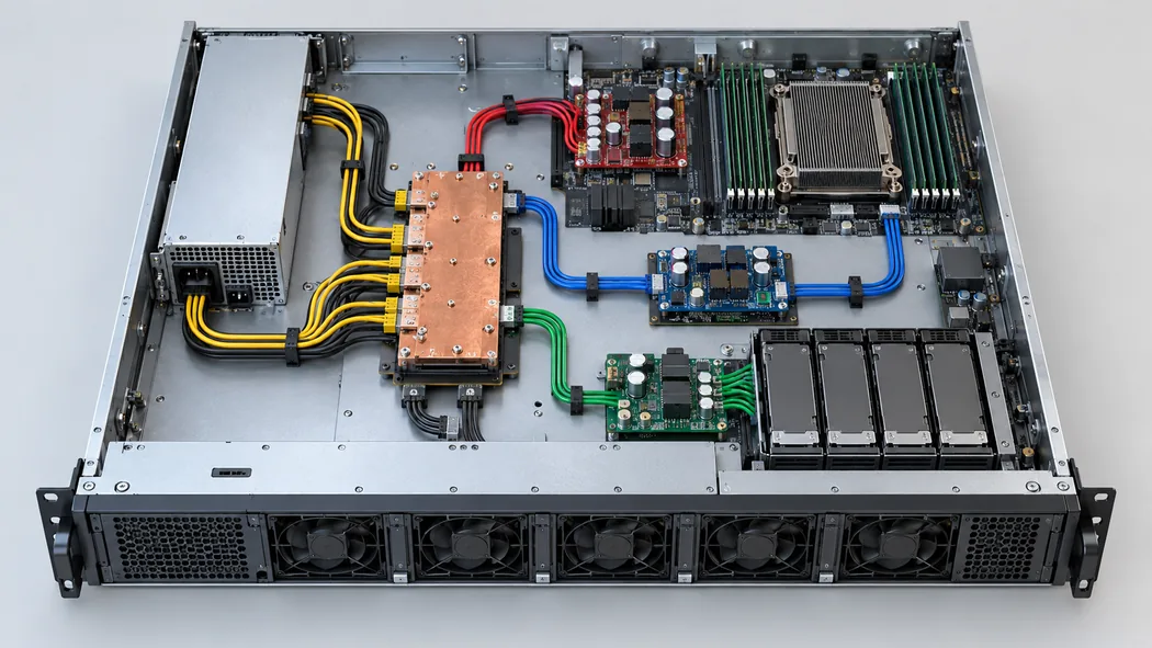
Load placement also matters. A server whose total demand remains below the supply’s headline rating can overload a single branch or connector group if power is unevenly allocated. Splitting loads across branches changes the local current, but it does not raise the module’s total available output. The host designer should use the actual board layout, connection ratings, and load profiles to resolve that distinction. Public product listings cannot establish a safe board trace width, contact count, or fuse choice for an unknown chassis.
Why 5 Vsb deserves its own path
Great Wall lists 5 Vsb at 2 A separately from the 12 V main output. Multiplication gives a nominal 10 W standby-rail scale, but the catalog does not state how that rail is counted in the 1600 W headline or what its timing and load regulation are. Standby power typically serves the small set of circuits that must operate while the main compute load is off, such as a board-management controller or power-control logic. Which circuits this particular module is intended to support depends on its detailed interface and the host design.
For a prospective host, the important distinction is electrical state rather than simply two voltage numbers. The management board may need a stable standby rail before it can issue an enable request for the 12 V path. After an orderly shutdown, it may continue to draw standby current even though the main rail is no longer supplying processors and drives. The exact sequence, enable pin, power-good behavior, and allowed standby loading cannot be inferred from the public catalog. They must come from the manufacturer’s controlled interface documentation and the receiving board’s power-state design.
A replacement with the correct 12 V capacity but an absent or incompatible 5 Vsb output could therefore appear dead to the host. The AC input may be present, yet the management controller never starts and the main rail never receives its enable condition. Conversely, a standby rail that powers the controller does not prove that the module can deliver the required 12 V current under load. These two failure modes are diagnostically different, so service procedures should measure and identify the rails separately using the documented connector assignment.
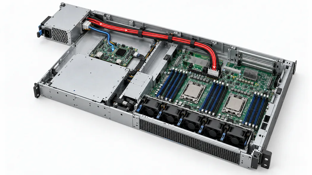
The 2 A standby entry is a maximum listed current, not a promise that every management configuration will work. A host may impose a startup surge, require a different standby tolerance, or expect a particular power-good and shutdown sequence. For an exact replacement, preserve the full part identifier and revision, then compare the host-approved part list. For a new design, obtain the standby timing and sequencing specification early enough to shape the management-board design rather than discovering an incompatibility during system bring-up.
Reading the two input ranges without assuming source transfer
The catalog lists 90–290 Vac and 192–288 Vdc as input windows. The DC interval is a high-voltage supply range; it is not a direct fit for a nominal 48 V battery plant. A 48 V site would need an appropriate conversion stage or a different supply designed for its source. The two ranges also do not establish that AC and DC can be connected simultaneously, that the module performs source selection, or that it can transfer between sources without interruption. Those are topology and connector questions, not consequences of two catalog entries appearing on one line.
The nominal 1600 W rating should not be presumed available at every point in either input window. At a fixed output load, a lower input voltage generally requires higher input current, allowing for conversion losses and AC power-factor behavior. Input components, wiring, and thermal limits may therefore constrain power near the low end of a range. Great Wall’s public entry does not provide a voltage-dependent power curve or an efficiency figure for GW-PA1600I. A facility or server design that depends on full output near 90 Vac or 192 Vdc needs the applicable datasheet and any derating conditions.
This distinction changes how a buyer describes the installation. It is useful to specify the source’s normal voltage, lowest sustained voltage, expected dips, frequency for AC, and protective arrangement rather than merely stating “AC compatible” or “DC compatible.” The required information is particular to the site. An installation whose AC source falls inside the published range at steady state can still need a hold-up or ride-through analysis if interruptions matter. No hold-up time is established by the public GW-PA1600I entry.
Hot-swap mechanics belong to the host interface
A live-serviceable module is part of a larger mechanical and electrical assembly. Guides position the module, the latch retains it, the connector mates at a controlled depth, and the receiving board manages the electrical transition. In a redundant host, the remaining source path has to carry the load while a module is absent. A single-module server can have a removable PSU without maintaining operation during removal. The phrase Hot Swap by itself does not distinguish these two service outcomes.
The public listing does not show GW-PA1600I’s dimensions, insertion path, keyed features, connector pin order, airflow direction, or live-removal control signals. These omissions matter more than a superficial resemblance between modules. If the module is shorter than a bay expects, its electrical connector may never fully mate. If a visually similar unit has a different pin assignment, insertion could present the wrong potential to a host circuit. If airflow is reversed, fans may oppose the server’s established cooling direction. These are interface risks, not claims about defects in GW-PA1600I.
For a maintenance spare, the host manufacturer’s approved part number is stronger evidence than a third-party photograph. The old module’s exact model, suffix, revision, and label should be compared with the replacement documentation. For a new chassis, the designer needs a controlled drawing before finalizing bay rails, latch clearance, rear access, connector seating, and ventilation. The resulting host design can then establish whether insertion and removal are supported under load and what happens to the 12 V and standby buses during that event.
A redundant pair raises a separate capacity question. Two modules listed at 1600 W do not automatically make 3200 W available after one fails. If one module must support the entire server following a loss, the surviving nominal capacity is one module’s rated output, subject to the manufacturer’s operating conditions and the host’s sharing arrangement. The public record does not confirm parallel operation, sharing controls, output isolation, or fault containment for this model. Those functions must be established by the module and backplane design together.
What the catalog can and cannot decide for a 12 V platform
GW-PA1600I is a relevant candidate where a host genuinely requires a 12 V high-current source, a 5 V standby rail, and a serviceable module interface. The exact published outputs make it more specific than a generic “1600 W power supply” search result. They also separate it from Great Wall’s 54 V and 53.5 V Hot Swap entries, which serve different downstream distribution arrangements. The catalog supports that architectural sorting before an engineering team spends effort on a detailed fit study.
It cannot approve a server, storage shelf, or rack system on its own. A complete application decision would require the controlled mechanical and connector drawings, rail tolerance and sequencing data, input-dependent output limits, cooling requirements, and the host’s load and service states. The detailed documentation should say which specifications apply to the exact orderable revision. Without that evidence, even an otherwise plausible 12 V replacement should remain a candidate rather than be represented as a drop-in spare.
The distinction is especially useful for procurement. A request that says only “1600 W hot-swap PSU” may attract unrelated 12 V, 48 V, or 54 V products with different connectors and standby provisions. Naming GW-PA1600I and the published 12 V/133.4 A and 5 Vsb/2 A entries narrows the conversation to the intended electrical class. Supplying the host model, existing PSU label, and mating-interface documentation then allows a supplier or system integrator to determine whether that class maps to an actual approved part.
The 12 V path is a 133 A-class distribution problem, and the standby path is a separate power-state problem. Each has distinct wiring, loading, timing, and diagnostic questions. Great Wall’s listing identifies both paths; the host interface and detailed manufacturer documents determine whether they can operate together in a particular machine.