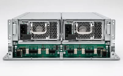
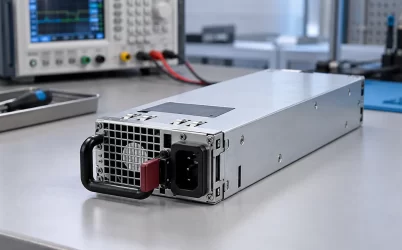
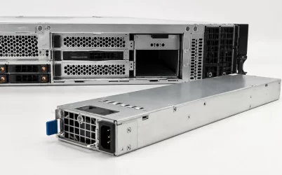
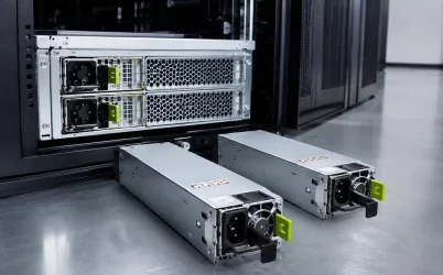
A 1U server with two power-supply modules is not necessarily able to continue operating after either module fails. The protected state depends on the server load, the capacity available from one supported PSU under the actual input and thermal conditions, the PDB and connector path, the independence of the upstream feeds, and the host’s response to a missing or faulted module. “Redundant” describes an architecture and a defined failure case; it is not a property established by the number of rear-panel handles.
For operators, the most useful question is direct: after one PSU or one input feed is lost, which server functions must remain available, for how long, and under what workload? Answering that question turns a vague 1U redundant power supply request into an operating envelope that can be matched to the exact server, module pair, rack power arrangement and service procedure.
One failed module changes the operating envelope
During normal operation, two supported modules may share the server load. After one is unavailable, the surviving module must carry the required DC demand by itself. Its input current and internal dissipation rise, its fan behavior may change, and every shared conductor between the module and the motherboard carries a different current distribution. The transition can also expose a workload excursion that was harmless while both modules were active.
The required load should be defined from server states rather than from a single nameplate total. Boot, storage spin-up, CPU or accelerator bursts, sustained application load, fan response and recovery activity can produce different demands. A protected 1+1 state does not need to preserve an impossible combination of every component maximum, but it does need to cover the credible states that the service and availability policy promises.
A server may respond to reduced power capacity by limiting processors or accelerators, preventing a configuration change, raising fan speed or initiating a controlled shutdown. Such behavior can be valid if it is documented and meets the application’s availability requirement. The important point is to distinguish uninterrupted full performance, uninterrupted reduced performance and graceful shutdown; all three are different outcomes.
Module redundancy and feed redundancy are separate
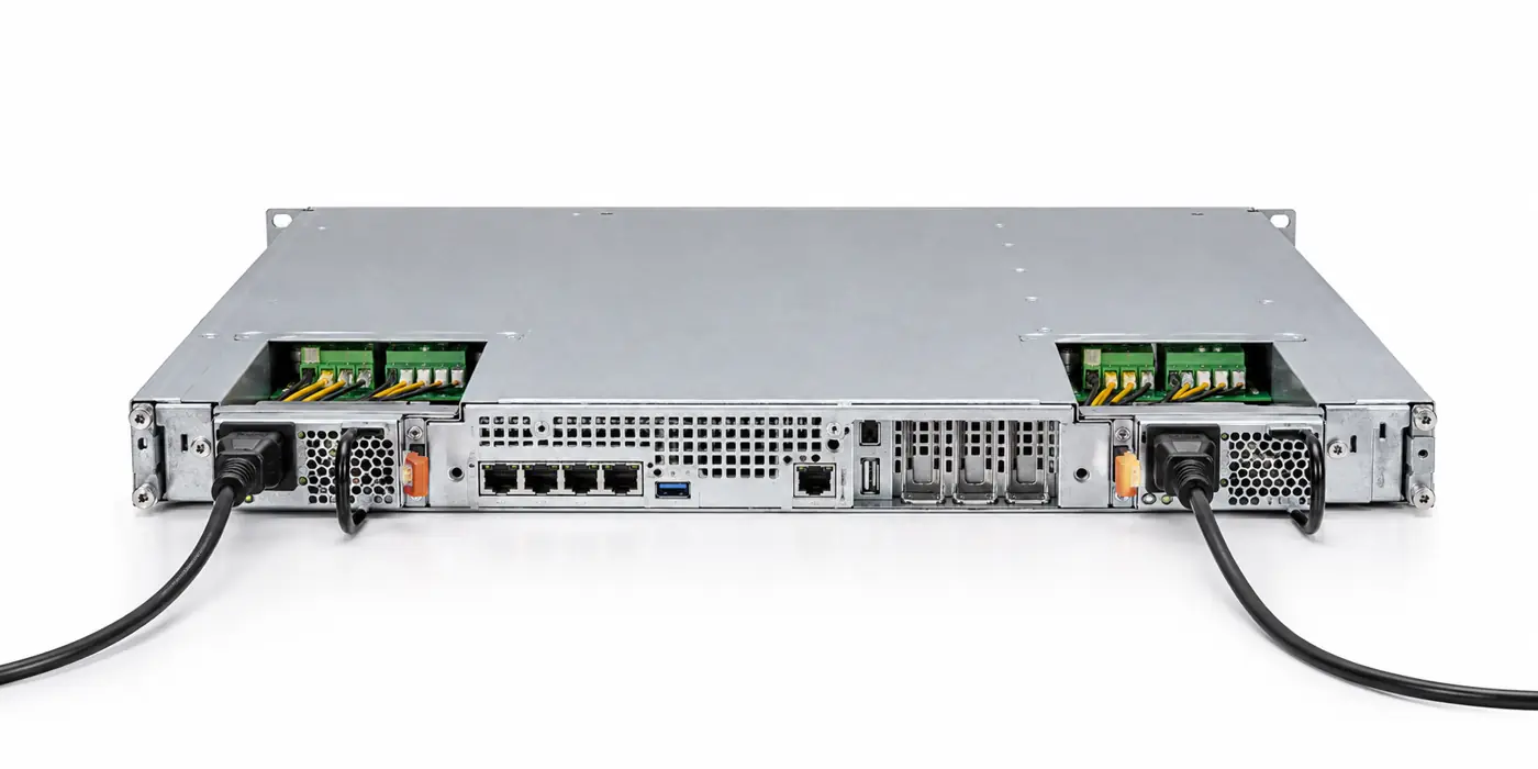
Two healthy PSUs connected to one upstream PDU or branch circuit can tolerate one module failure but not loss of that common source. If the rack design requires protection from a feed failure, each module should be connected to the intended independent source domain, subject to the server manufacturer’s supported input arrangement and the facility’s electrical design.
Independence should be traced beyond the visible cords. Two receptacles may return to the same breaker, UPS output or maintenance bypass. Conversely, two genuinely independent feeds may have different voltage conditions or transfer behavior that affect the available PSU output. The server power plan should identify the source for each inlet, the failure being covered and the load that shifts to the surviving feed.
The downstream side also contains shared elements. Both modules may mate with one cage and one PDB before power reaches the motherboard. A module failure can be isolated while a PDB short remains a common failure. Redundancy claims should therefore name the boundary: module loss, cord loss, branch loss, PDU loss or another specified event.
The 1U chassis makes airflow part of redundancy
A 1U enclosure has little vertical space for fan area, heatsinks, connector clearance and cable routing. PSU airflow is usually coordinated with the server fan wall and the direction of rack cooling. A replacement module with an incompatible airflow direction can recirculate exhaust or oppose the chassis pressure plan even when it fits mechanically.
The single-module state is the difficult thermal condition. The surviving converter handles more load, while the failed module or empty bay may stop contributing airflow. If a removed PSU leaves an open path between hot and cold zones, a blanking device or host airflow response may be required. Temperature should be checked at the module inlet and at high-current PDB components, not inferred only from the cold-aisle setpoint.
Rear service clearance also affects cooling. A tightly bent cord, cable-management arm or rack door can obstruct a small PSU exhaust. The installation review should show both modules, cord routing, latch travel, extraction path and nearby rack equipment. “1U” identifies the server height; it does not guarantee that any nominally compact redundant PSU will fit the bay or breathe correctly.
Current sharing is not the availability proof
Supported modules may use a current-share function to divide load in normal operation. Balanced sharing can reduce temperature and keep both units away from their limits. However, a current-share specification does not establish that one unit can carry the full required load, and telemetry showing similar current does not prove that the pair is connected to independent feeds.
The availability proof follows the surviving path. It starts with the documented output available from one exact module at the deployed AC input and inlet condition. It then accounts for the PDB’s isolation elements, connectors, copper and branch protection before reaching the server load. Any firmware-enforced power cap or host population rule also belongs in the evaluation.
Mixing superficially similar modules can undermine sharing and management behavior. Differences in revision, firmware, airflow, supported host option or communication implementation may matter even when the mechanical envelope and headline wattage match. Use the server manufacturer’s approved pairing and replacement information rather than treating a family resemblance as permission to mix.
Monitoring should describe the degraded state clearly
A useful alert identifies which module or input is affected, whether output remains available, and whether the server has entered a reduced-capacity state. A generic “power supply warning” can lead technicians to remove the wrong module or overlook an upstream feed problem. Local LEDs, BMC events, telemetry and facility monitoring should be interpreted together within their documented capabilities.
Alarm logic also needs persistence and suppression rules. A brief input disturbance may create several related events as the PSU, PDB and host controller react. Correlating timestamps helps distinguish a failed module from a rack power interruption or thermal protection event. Monitoring is evidence about behavior; it does not expand the electrical capacity of the remaining path.
Operators should know what changes are expected after the fault: fan speed, power cap, warning state, workload response and permitted service window. This information allows the incident procedure to prioritize recovery without claiming that redundancy removes all urgency.
Hot swap is a controlled service state
Hot swap means the complete supported system permits a module to be removed and replaced while the server remains energized under specified conditions. It requires output isolation, connector sequencing, safe touch conditions, host recognition and adequate capacity from the surviving path. A removable module is not automatically hot-swappable in every chassis.
Before removal, the technician should confirm the failed identity using the host interface and the physical indicator, verify that the other module is healthy and connected to the intended source, and ensure that current load is inside the supported single-module envelope. The service path must be clear so the healthy cord, latch and exhaust remain undisturbed.
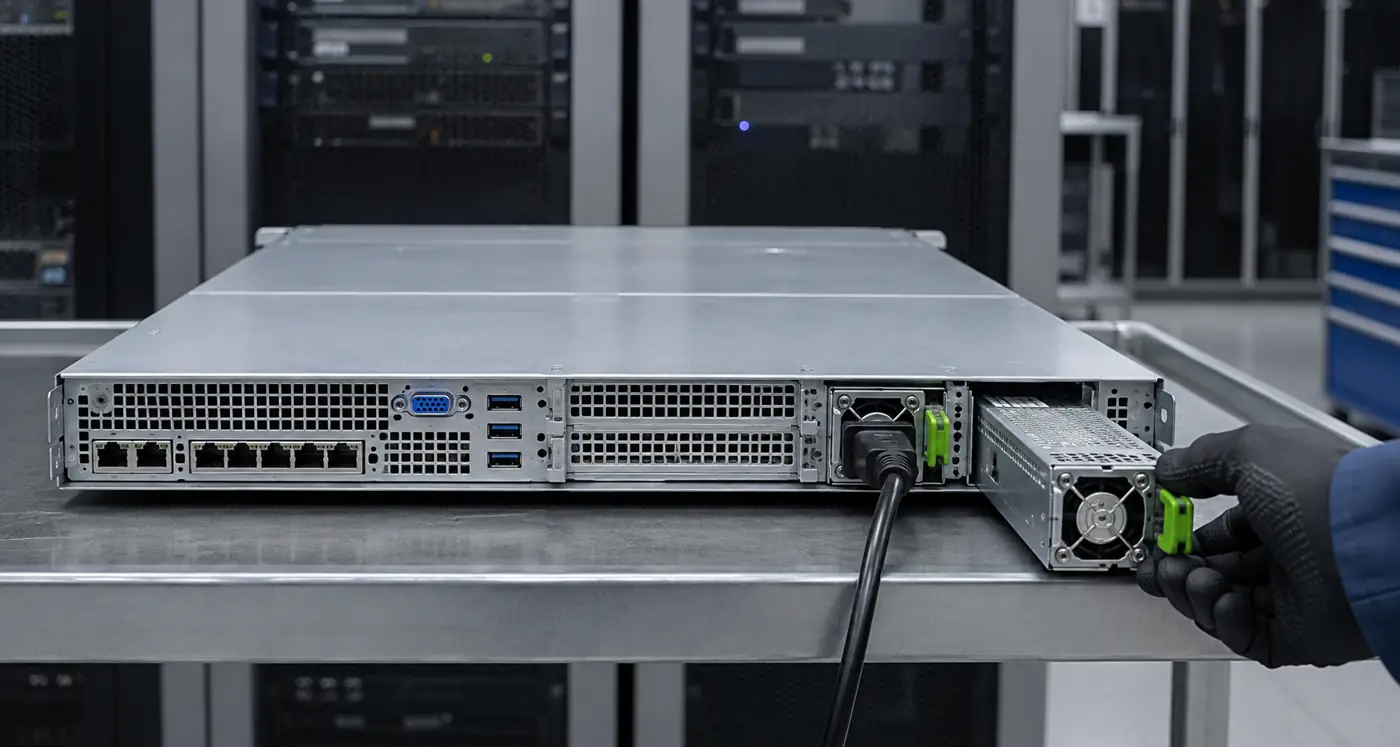
After insertion, recovery is more than an LED turning green. The host should recognize the replacement, clear or update the relevant event, resume the supported sharing state and show stable input and output information where available. If the replacement is a different approved revision, the service record should preserve that identity for future troubleshooting.
The replacement interval also changes risk. While only one module is available, a second module fault or loss of its upstream feed can remove server power. Operations teams should therefore avoid unnecessary workload or configuration changes during the degraded window and restore the supported pair within the service objective defined for the platform. Redundancy provides time to act; it does not make the remaining path failure-proof.
Replacement selection starts with the host identity
For an existing 1U server, the safest route is the documented service part or supported supersession for the exact platform and chassis revision. Compare the complete ordering identifier, revision rules, connector and keying, latch, airflow direction, input conditions, output capability, management support and whether the quotation includes one module or a larger assembly.
For a new server design, the integrator must control the cage, PDB, module interface, source arrangement, thermal path and service behavior. A CRPS family or similar modular architecture can narrow the design space, but exact mating records and host behavior still need to be defined. Procurement should not separate the converter from the hardware that makes redundancy possible.
A credible 1U redundant server power supply specification therefore states the promised failure state and the remaining service level. It shows that one supported module and the complete shared path can carry the required load, keeps feed independence distinct from module redundancy, and treats airflow and live replacement as parts of the same operating design. When those conditions are explicit, two PSU bays become an availability feature rather than an ambiguous product label.
The same definition should appear in operations documentation so that engineering, facilities and service teams are working from one failure boundary.