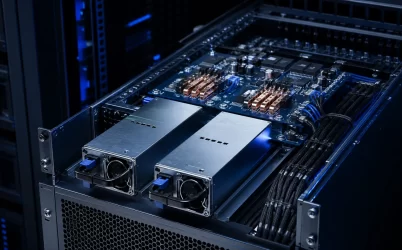
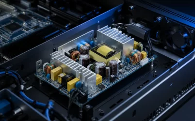
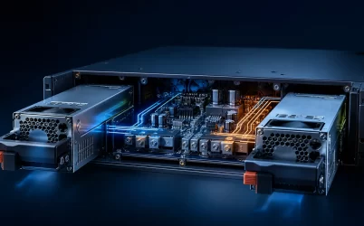
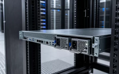
A server redundant power supply is a power subsystem designed so the server can continue operating after a defined PSU or input-path failure. Selection is not based on installing two modules alone. The remaining online supply capacity must support the server’s maximum validated load, while the CRPS modules, power distribution board, connectors, airflow, firmware, and facility feeds remain compatible. For common 1+1 operation, either supply must be capable of carrying the required load after its partner is removed. Systems with higher base power may instead use N+1, 2+2, or another platform-supported policy.
Quick Answer
Choose a server redundant power supply by calculating capacity after the intended failure, not by adding all installed PSU wattages. Confirm the server’s supported redundancy mode, approved PSU family, input-voltage derating, output bus, PDB interface, airflow direction, hot-swap behavior, and BMC telemetry. For end-to-end resilience, connect redundant modules to independent A and B power paths with each path sized for the post-failure load. A design is genuinely redundant only when the surviving PSU, PDB path, cables, rack PDU, and upstream source can all carry the required load within their supported limits.
Define the Failure the Server Must Survive
“Redundant” is incomplete unless it names a failure boundary. A two-module server may tolerate one PSU hardware failure but still stop if both modules share one rack PDU, one branch circuit, or one upstream UPS. Conversely, a platform connected to independent feeds may still lose redundancy if its operating load exceeds the capacity remaining after one module is removed.
Start by defining which events the system is expected to ride through:
- loss or removal of one power supply module;
- loss of one AC feed, rack PDU, branch circuit, or UPS path;
- failure of one PDB input path or connector, when the platform architecture supports isolation;
- maintenance replacement of a module while the workload remains online;
- a fan, temperature, input-voltage, or internal protection event that causes one module to reduce output or shut down.
This definition becomes the engineering constraint. It determines how many modules are required, how much capacity must remain, whether independent facility feeds are necessary, and which failure tests belong in platform validation.
Match the Redundancy Mode to the Workload
| Configuration | Normal Meaning | Appropriate Condition | Main Limitation |
|---|---|---|---|
| 1+0 | One required module, no PSU redundancy | Low-cost or noncritical system where interruption is acceptable | Module or feed loss can stop the server |
| 1+1 | One module supports the load and one provides redundancy | Common dual-PSU server architecture within one-module capacity | Usable redundant capacity is limited by the supported output of one module |
| 2+0 | Two modules provide combined nonredundant capacity | Platform load exceeds one-module capacity and redundancy is not required | Losing one module can force throttling or shutdown |
| N+1 | N modules carry the required load and one additional module is available | Higher-power platforms requiring more than one active module after a failure | Capacity and control logic depend on the specific server architecture |
| 2+2 or N+N | Two power groups can support the defined load independently | Platforms designed for multiple-module or source-path redundancy | Requires compatible chassis, distribution, controls, and facility feeds |
These terms describe capacity policy, but exact behavior is platform-specific. Some servers automatically move between redundant and combined-power modes as load changes. Some may throttle or initiate an orderly shutdown when redundancy is lost. Use the server technical documentation and management settings to confirm the supported policy rather than assuming the notation has identical behavior across manufacturers.
Calculate Capacity in the Failure State
Consider a hypothetical server with a validated maximum sustained DC load of 1,800W. Two 2,400W modules are installed in a platform that officially supports those modules in 1+1 mode at the intended input voltage and temperature.
During ideal balanced operation, each module may supply approximately:
1,800W ÷ 2 = 900W per module
After one module fails or is removed, the surviving module must supply the full 1,800W. Its utilization becomes:
1,800W ÷ 2,400W = 75%
The redundant system capacity is therefore 2,400W under these stated assumptions, not 4,800W. The server has 600W of module-rating margin in the failure state before considering any required platform reserve, transient demand, input-voltage derating, thermal derating, or vendor power-budget rules.
This calculation must use the maximum output supported under the real input and cooling conditions. A module’s available output may depend on line voltage, ambient temperature, altitude, airflow, or chassis policy. If the platform’s worst-case load becomes greater than one module’s supported capacity, two installed modules may operate as 2+0 rather than preserve 1+1 redundancy.
Extend Redundancy Through the A and B Power Paths
Internal PSU redundancy does not by itself protect against a shared upstream failure. For a dual-cord server, a common approach is to connect PSU A to one rack PDU and PSU B to a separately supplied rack PDU. The degree of independence can extend through branch circuits, UPS systems, switchgear, and facility sources according to the availability target.
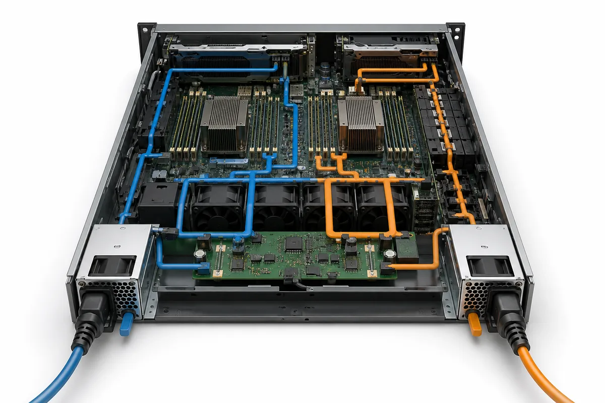
Each surviving path must be sized for the transferred load. Returning to the hypothetical 1,800W server, a balanced state may place roughly half the server load on each input path, depending on the server’s power policy. After path A fails, path B may need to carry the entire server input demand. Rack-PDU and branch-circuit calculations should therefore use the supported failure-state demand, not only the normal balanced reading.
Power policies can complicate monitoring. Some systems share load approximately evenly, while others place one supply in a low-load or standby state to improve efficiency. That operating choice may create intentionally unequal A/B current. Facility alarms should distinguish a supported efficiency mode from a failed feed, and operators should confirm that the standby module can return to active operation within the platform’s specified behavior.
Verify Electrical, Mechanical, and Management Compatibility
Two server PSUs with similar dimensions and wattage are not necessarily interchangeable. Compatibility includes mechanical length, connector location, keying, output voltage, standby power, pin definition, current-sharing method, management protocol, airflow direction, firmware expectations, and approved power distribution board combinations.
Common Redundant Power Supply specifications can standardize important elements, but a CRPS form factor does not establish universal drop-in support. A specific server may approve only certain module families or firmware combinations. The system controller may reject, derate, or report errors for an unsupported pair even when the modules physically fit.
Review the CRPS and power distribution board relationship as one subsystem. The PDB carries high current, routes standby and control signals, and connects the removable modules to server loads. Its connector rating, copper paths, protection, telemetry routing, and thermal behavior must remain within limit during both normal sharing and single-module operation.
Account for Transients, Thermal Limits, and Efficiency
Server power budgets should include more than sustained average demand. Processor and accelerator load steps, drive startup, fans, and other dynamic loads can create brief peaks. The CRPS control loop, PDB impedance, bulk capacitance, connectors, and point-of-load converters work together to keep the distribution bus within the platform limits.
The selection consequence is to validate representative load steps in both normal and failure states. A pair of modules may respond acceptably while sharing, yet the single surviving module can experience a larger transient step immediately after its partner disconnects. Avoid substituting an arbitrary percentage margin for the platform’s supported transient and power-budget data.
Thermal conditions can also change after a failure. One module carries more current, its fan control may change, and the empty bay can alter chassis airflow. A correctly installed PSU blank may be required when a bay is unused because the blank forms part of the intended air path. Validate inlet temperature, exhaust temperature, PDB hotspots, connector temperature, and downstream component cooling with the chassis covers and air ducts installed.
Efficiency matters because conversion loss becomes heat, but the highest headline efficiency class is not automatically the best choice for every server. Compare supported efficiency across the expected load range and input voltage, together with thermal margin, acoustic requirements, power density, availability, and platform approval.
Confirm Hot Swap and Failure Recovery
Hot swap means a supported module can be replaced while the system remains powered by the surviving path. It depends on controlled connector sequencing, inrush management, output isolation, firmware handling, and sufficient remaining capacity. A removable handle alone does not establish hot-swap support.
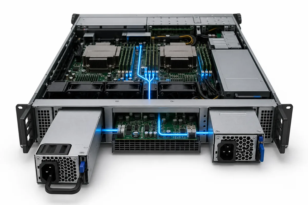
Test removal and insertion at representative load, and confirm that the BMC records the event, identifies the failed bay, preserves the surviving module within limit, and restores the intended redundancy state after replacement. Service procedures should specify approved module combinations, cord sequencing, latch operation, and verification of LEDs and event logs.
Telemetry can expose input status, output power, temperature, fan condition, warnings, and faults when supported, but available fields and control behavior vary by module and platform. PMBus support should be treated as an interface capability, not universal interoperability. Verify the required commands, addressing, scaling, inventory data, and fault responses with the actual BMC implementation.
Choose by Deployment Scenario
| Scenario | Primary Decision Factor | What to Verify |
|---|---|---|
| AI or GPU server | High sustained power and rapid load change | Failure-state capacity, transient response, high-line requirements, PDB and connector temperature |
| Storage server | Drive startup and availability during service | Startup power, branch distribution, hot swap, and post-failure voltage stability |
| Edge or telecom server | Compact chassis and constrained environment | Input source, airflow direction, derating, noise, and remote monitoring |
| Enterprise server | Compatibility and operational continuity | Approved PSU pairs, 1+1 policy, A/B cabling, BMC alerts, and replacement process |
Selection and Validation Checklist
- Define the PSU, input-feed, and upstream failures the system must survive.
- Calculate maximum sustained and transient load after the defined failure.
- Confirm the platform-supported redundancy mode and module count.
- Use the PSU output available at the actual input voltage, temperature, altitude, and airflow.
- Verify module, PDB, connector, voltage, firmware, airflow, and management compatibility.
- Size each A or B input path for the load it must carry after transfer.
- Test current sharing or standby behavior, load steps, module removal, insertion, faults, alarms, and thermal limits.
- Document approved replacement parts and the procedure for restoring redundancy.
After the server requirements are fixed, Powernexu’s verified CRPS power supply category provides a relevant place to compare available module families. Final selection should remain tied to the server’s approved electrical, mechanical, thermal, and management interface.
Frequently Asked Questions
Does a redundant power supply double server wattage?
Not in a typical 1+1 configuration. One module must support the required load after the other is lost, so redundant capacity is based on one module’s supported output under the actual conditions. A platform may support combined 2+0 power, but that operating mode does not preserve one-module redundancy.
Do both server power supplies carry load at the same time?
They may share load, or one may carry most of it while the other operates in a supported standby or hot-spare mode. The behavior depends on platform policy, firmware, and compatible PSU capabilities.
Can different wattage server PSUs be used together?
Some hardware might power on with mixed modules, but many server platforms require an approved matching pair for redundancy and may report errors or disable redundancy when modules differ. Follow the specific server’s supported configuration rather than assuming physical fit is sufficient.
Are two power cords enough for full power redundancy?
Two cords protect against more failures only when they connect to suitably independent, correctly sized power paths. If both terminate at the same rack PDU, branch circuit, or UPS, that shared component remains a common failure point.
A dependable redundant power design is an end-to-end capacity and failure-domain decision. The supplies, distribution board, server controls, chassis cooling, cords, rack PDUs, and upstream sources must be evaluated together against the interruption the workload is expected to survive.