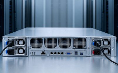
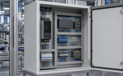
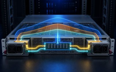
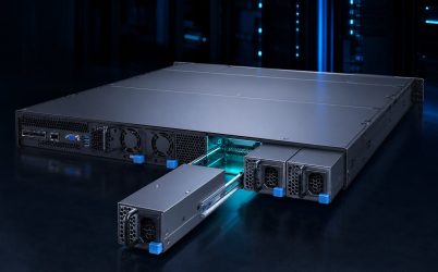
Server power supply requirements should be written as an interface and operating envelope, not as a shopping list of wattage, efficiency, and connector type. A server PSU must accept the facility source, maintain the DC bus through workload changes, fit and cool within the chassis, coordinate with the PDB and BMC, isolate faults in redundant service, and comply with the intended regulatory environment. The requirement set becomes useful when every statement has a condition, an acceptance limit, and a way to demonstrate compliance. This article shows how to build that set from the server outward.
Requirement group 1: identify the server configuration
Freeze the processors, memory, storage, network adapters, accelerators, fans, and expansion options covered by the power requirement. Include supported future configurations if they genuinely belong in the product plan. A vague “maximum server” assumption can create unnecessary oversizing or miss a specific high-transient option.
For each configuration, establish idle, typical, sustained maximum, startup, and fast excursion behavior. State which workloads or synthetic tests represent acceptance. The PSU requirement should support the platform’s permitted envelope, not an unrelated sum of every component’s marketing maximum.
Requirement group 2: facility input
Specify AC or DC input range, frequency where applicable, maximum current, inrush, power factor, leakage, ride-through, inlet, cord, and protective-device assumptions. If full output is available only over part of the input range, state the capacity at each supported region. International and laboratory use may expose the server to low line even when production racks use higher voltage.
For redundant systems, identify A/B source expectations. Two PSU bays do not require independent feeds by themselves, but the availability requirement may. The surviving PDU and branch must carry transferred input current without overload.
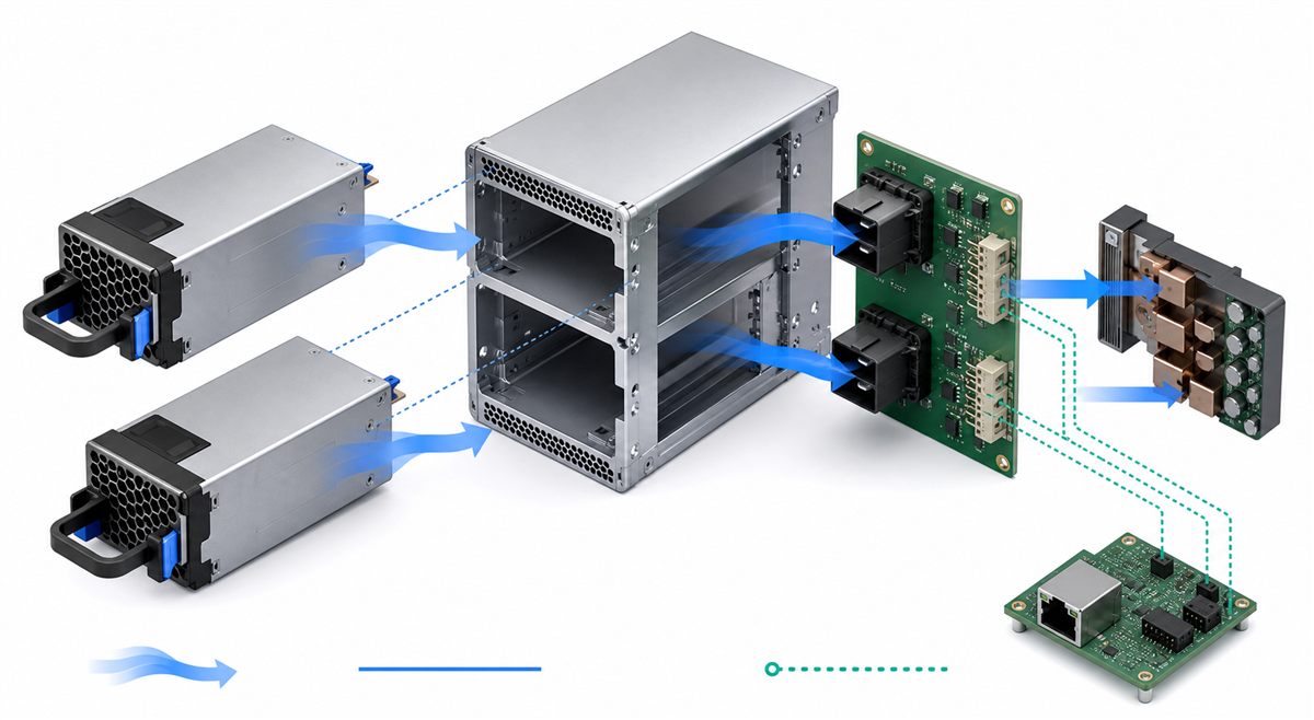
Requirement group 3: output and dynamics
Define the main and standby rails, regulation, continuous current, ripple, capacitive load, remote sense, startup, shutdown, discharge, and protection. Dynamic requirements should name the load-step magnitude, slew rate, allowed voltage deviation, and recovery. Use conditions that represent the server bus and downstream converters.
Peak capacity requires duration and repetition. An overload feature cannot be treated as continuous output. State the expected current-limit mode and recovery because hiccup, foldback, constant-current, and latch-off responses affect boot and fault behavior differently.
Requirement group 4: mechanical interface
Provide a controlled drawing with height, width, depth, connector datum, guides, keying, latch, handle travel, insertion force, extraction clearance, and tolerance. Include airflow direction, grille keep-out, indicator visibility, and cord-retention space. The module should seat fully without using the connector to correct chassis misalignment.
Mechanical requirements also cover service in the rack. A technician should reach the latch and extract a module without disconnecting unrelated cables. A deeper alternate can violate internal clearance even if the rear opening matches.
Requirement group 5: connector and signals
Define every power, return, standby, sense, enable, power-good, present, fault, current-share, address, and communication contact. Include direction, logic level, pull-up, current, default state, timing, and disconnect behavior. Contact sequence and current derating belong in the interface.
Do not state merely that the PSU is “CRPS compatible.” Name the governing document and revision, then document host-specific options. A pinout from a visually similar module is not an acceptable substitute.
Requirement group 6: efficiency and thermal behavior
Set efficiency targets by applicable certification category or measured operating points. Link them to input and load. Include thermal derating, maximum inlet temperature, altitude, airflow impedance, fan control, acoustic expectations where relevant, and behavior after one redundant module is removed.
Conversion loss becomes heat, but internal component temperature also depends on topology and airflow. Require temperature limits at defined locations or compliance with the supplier’s thermal conditions, then test in the production chassis.
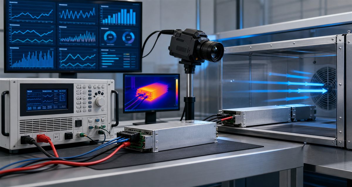
Requirement group 7: redundancy and hot swap
State the configuration—1+1, N+1, or another mode—and the maximum load that remains supported after the defined failure. Include current-share tolerance, output isolation, reverse-current limits, transfer behavior, input-feed grouping, and degraded-state thermal operation.
If hot swap is required, specify live removal and insertion conditions, connector sequencing, inrush, bus disturbance, management events, and service procedure. Removability alone does not satisfy a hot-swap requirement.
Requirement group 8: management and firmware
List required PMBus commands, revision or subset, addressing, data formats, telemetry accuracy, update rate, warning and fault bits, identity fields, fan control, and BMC acceptance. State behavior when one module or the bus is unavailable. A generic PMBus checkbox cannot define the host contract.
Firmware policy should cover approved revisions, mixed-module operation, update method if supported, and rollback or replacement. Record the BMC version used for qualification because host behavior can change with firmware.
Requirement group 8A: workload power controls
Modern server platforms may use processor limits, accelerator power caps, fan policies, or chassis-level budgeting to remain inside available power. If these controls are part of the supported envelope, state their maximum response time, authority, default behavior, and state after BMC reset. A software limit that acts after the DC bus has already fallen cannot replace adequate transient capability.
Define behavior when installed hardware exceeds the redundant power budget. The platform might block a configuration, reduce performance, warn the operator, or allow nonredundant operation. This policy should be visible to procurement and operations so a later component upgrade does not silently remove the intended availability.
Requirement group 8B: rack and facility interaction
Specify the supported inlet and cord, rack PDU receptacle, branch voltage, and expected A/B connection. Maximum server input under failover matters because one feed can receive the whole load. If many servers transfer together, facility planning must account for aggregate current rather than a single chassis.
Rack conditions also affect cooling. Rear-door clearance, cable bundles, neighboring exhaust, and vertical PDU position can raise the PSU inlet temperature or block module removal. Include these constraints in installation requirements instead of treating them as unrelated facility details.
Requirement group 9: protection and abnormal states
Specify overvoltage, overcurrent, short-circuit, overtemperature, fan fault, input fault, and communication fault behavior as applicable. Include threshold range, delay, shutdown mode, retry or latch, output isolation, alarm, and recovery. Coordinate PSU protection with PDB and downstream protection.
Abnormal tests should follow safe procedures and applicable standards. The requirement is not to create arbitrary destructive tests but to demonstrate defined fault containment and system response.
Requirement group 10: evidence and change control
| Evidence | Requirement area |
|---|---|
| Datasheet and curves | Input, output, efficiency, thermal, protection |
| Mechanical and connector drawings | Fit, seating, pinout, current path |
| Certification reports | Exact model and applicable scope |
| PMBus command file | Management contract |
| Host test report | Dynamic, redundant, thermal, and firmware behavior |
| Approved configuration record | Revision and substitution control |
Define which changes require partial or full requalification: hardware revision, firmware, fan, connector, PDB, BMC, chassis airflow, input range, or load configuration. Supplier notification and procurement controls keep production units aligned with the tested baseline.
Convert requirements into test cases
- Give each requirement a unique identifier and measurable condition.
- Assign verification by inspection, analysis, certificate review, or test.
- Define equipment, setup, operating point, acceptance limit, and recorded evidence.
- Cover nominal and boundary conditions without duplicating tests unnecessarily.
- Trace failures back to the specific requirement and corrective revision.
- Retest affected interfaces after any approved change.
This traceability prevents an impressive demonstration at one operating point from being mistaken for full compliance. It also makes supplier comparison more objective.
Use tolerance and margin deliberately
Each requirement should distinguish a hard operating limit from design margin. Margin can absorb measurement uncertainty, aging, component tolerance, load growth, or environmental variation, but an arbitrary percentage applied to every field can oversize the system or create contradictory requirements. Explain the risk each margin addresses.
Combine worst cases only when they can occur together. Maximum load, minimum input, maximum inlet temperature, high altitude, and one failed PSU may form a legitimate corner for some deployments. In others, particular conditions are mutually exclusive. A condition matrix prevents both under-testing and impossible test combinations.
Supplier responses should expose exceptions
Ask suppliers to answer each clause as compliant, compliant with stated condition, or noncompliant, with a document reference. A blank or general brochure should not count as evidence. Exceptions can then be evaluated for actual system impact instead of disappearing inside a general claim of compatibility.
When two candidates satisfy mandatory requirements, compare measured efficiency, thermal margin, telemetry quality, service, lead time, warranty, cost, and standardization. This order keeps commercial comparison from overriding an unresolved technical interface.
Production acceptance protects the qualified baseline
Incoming or production checks may confirm part number, revision, connector and keying, firmware identity, output and standby behavior, PMBus communication, fan direction, and visual condition. The scope follows manufacturing risk and supplier controls; it need not repeat every qualification test on every unit.
Maintain traceability from server serial or build configuration to approved PSU revision where availability or regulatory evidence requires it. If field failures reveal a new condition, update the requirement, test, and service documentation together rather than applying an undocumented workaround.
Separate mandatory requirements from preferences
Mandatory clauses protect function, safety, compatibility, or the availability target. Preferences may address energy, acoustics, service convenience, standardization, or cost. Mixing the two can disqualify a technically suitable unit for a minor preference or allow a low-price offer to omit a critical interface.
Powernexu’s server power supply specifications reference explains how to interpret common datasheet fields. The CRPS specification checklist provides deeper detail for common redundant modules.
The requirement package is complete when it supports a decision
A good server power supply requirement set lets engineering approve or reject a candidate without guessing. It states the server configuration, operating limits, physical and electrical interfaces, management contract, redundancy behavior, environmental conditions, evidence, and change policy. It should be precise enough for acceptance while avoiding invented limits that the server does not need. The final result is a controlled boundary between facility, PSU, PDB, chassis, firmware, and workload.