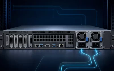
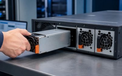
A 24V open frame power supply is an AC-DC converter built on an exposed circuit board for installation inside another product or enclosure. The 24 V output is a design target for controls, relays, sensors, valves, communications equipment, and motor interfaces; it does not define current, wattage, cooling method, safety approval, or connector style. Selection begins by translating every 24 V load into steady current, startup behavior, wiring drop, and allowable ripple, then placing the board in an enclosure that supplies mechanical protection, grounding, airflow, and final-equipment compliance.
Start with the 24V bus, not the headline wattage
Industrial designers often arrive at this category because the loads already speak 24 V: a PLC, remote I/O, relay coils, proximity sensors, small actuators, control valves, or a communications subsystem. The supply’s job is not merely to produce a nominal voltage. It must hold the load terminals inside their permitted range while current changes, conductors introduce voltage drop, and neighboring loads switch.
Current is the useful common language. A 120 W output at exactly 24 V corresponds mathematically to 5 A, while 240 W corresponds to 10 A. Those examples explain the relationship only; they are not recommended sizes and do not describe a specific model. Published output limits may change with input voltage, airflow, mounting orientation, ambient temperature, or whether the supply is installed with an optional cover or fan.
| Load behavior on the 24V bus | What the supply experiences | Design consequence |
|---|---|---|
| PLC, I/O, and sensors | Mostly continuous demand with state-dependent variation | Budget steady current and acceptable rail noise |
| Relay or solenoid coils | Step changes and inductive turn-off energy | Account for simultaneous switching and suppression placement |
| Motor or actuator interface | Starting current and repeated dynamic demand | Use the documented peak capability and duration, if provided |
| Long field wiring | Voltage loss in outgoing and return conductors | Evaluate voltage at the load, not only at PSU terminals |
Combining these loads requires timing as well as arithmetic. Five valves that never energize together do not create the same demand as five commanded simultaneously. A controller that boots before an actuator can sequence the bus differently from a design in which every branch starts at once. The load profile should represent real machine states: power-up, idle, motion, alarm, restart after a brownout, and controlled shutdown.
A 24V rail is a distribution system inside the machine
The output terminals are only the start of the rail. From there, current passes through conductors, fuses or electronic protection, terminal blocks, connectors, and returns. Each segment has resistance. At higher current or longer distance, the voltage reaching a remote device can be meaningfully lower than the voltage measured at the power board.
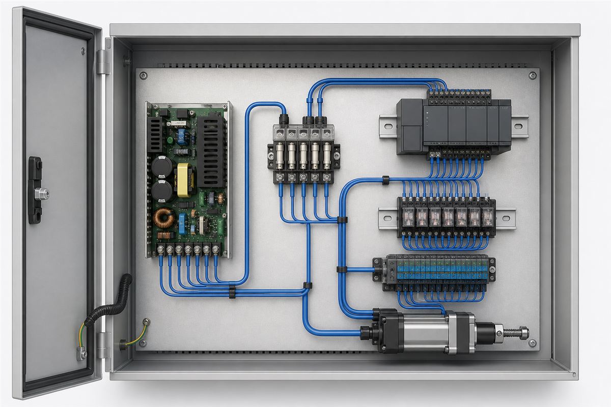
Remote sense, where an exact model provides it, can compensate for some distribution drop by regulating at designated sense points. It cannot make an undersized conductor safe, and careless sensing can raise voltage elsewhere on a lightly loaded bus. Sense leads require the routing, protection, and connection method in the manufacturer’s instructions. If remote sense is absent, conductor sizing and terminal placement carry more of the regulation burden.
Branch protection deserves equal attention. A large source can deliver much more current into a small sensor cable than that cable should carry. Separate protection can limit the effect of a shorted field device and make faults easier to isolate. The coordination method depends on the supply’s current-limit behavior, the protective devices, conductor ratings, and the intended equipment standard; a generic 24 V label cannot determine it.
Open frame transfers enclosure duties to the product designer
An enclosed DIN-rail supply arrives with barriers, touch protection, mounting provisions, and airflow assumptions built into its housing. An open-frame board deliberately leaves much of that integration to the host product. Mains terminals and primary-side circuitry may be accessible whenever the host cover is open. The final enclosure must prevent unintended contact in normal use and foreseeable service conditions.
Mounting hardware is part of the electrical design. Standoffs must support the PCB without flexing it, maintain the manufacturer’s required spacing beneath and around the board, and avoid contacting traces or components. Screw heads, washers, conductive chassis features, cable shields, and nearby boards can reduce clearance unexpectedly. Board dimensions alone therefore do not prove mechanical fit.
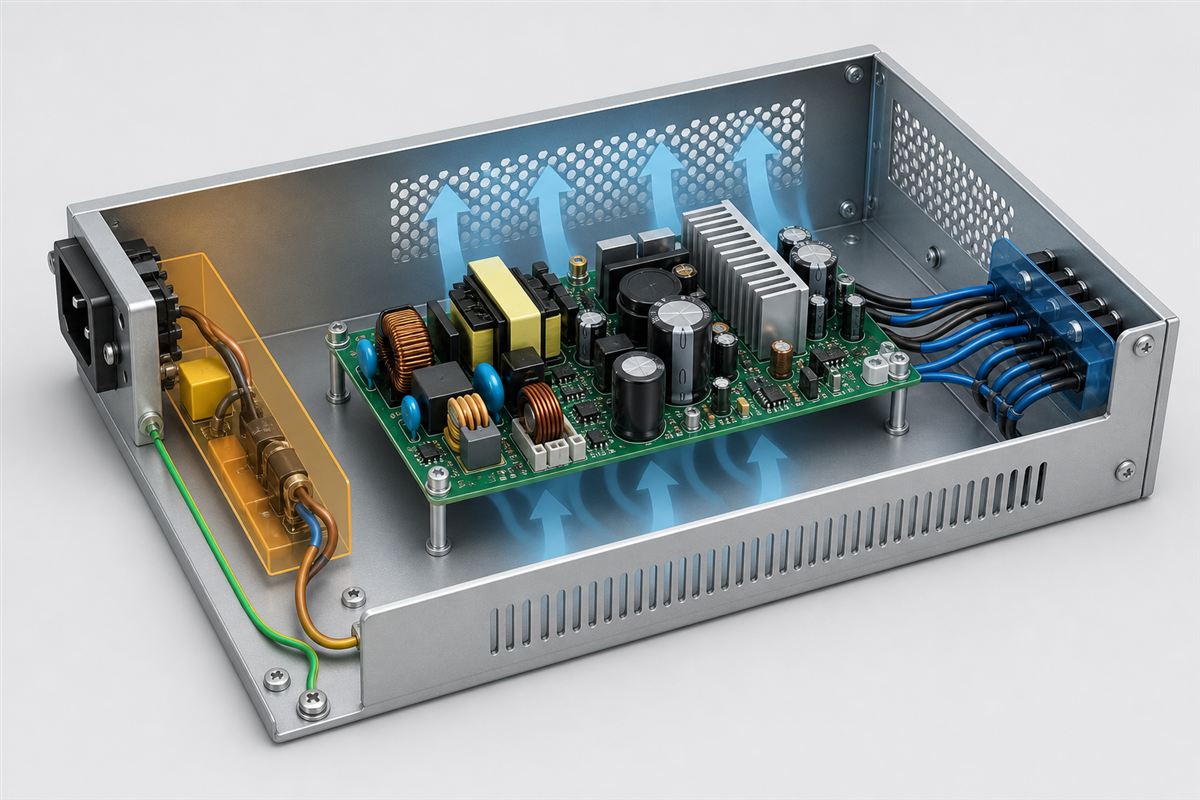
Protective earth should follow the supply and final-equipment instructions. A metal enclosure commonly needs a dependable protective bond, while an identified earth point on the PSU may also require connection. Functional grounding for EMC and protective earthing for shock safety can interact, but they are not interchangeable concepts. The wiring route should be short and mechanically secure where the applicable design calls for it.
The AC-DC open-frame embedding article covers the broader primary-side safety boundary. In a 24 V design, that boundary remains critical even though the output is low voltage: the board still converts hazardous mains inside a host enclosure.
Cooling determines how much 24V current is actually available
Open-frame ratings are closely tied to airflow and temperature. A datasheet may distinguish natural convection from forced-air operation, specify an airflow direction or measurement location, and publish derating above a stated ambient condition. Those details are model-specific. A fan elsewhere in the cabinet does not automatically reproduce the test condition at the PSU.
Component placement shapes the path. Air needs to reach heat sinks, magnetics, rectifiers, and other temperature-critical areas without being short-circuited through a nearby opening. Tall wiring ducts, adjacent PCBs, cable bundles, and enclosure walls can create sheltered hot zones. Orientation can change buoyancy and the way heat collects beneath a cover.
The useful output rating is the rating supported in the finished enclosure. If a model supplies more current with forced air than by convection, the design should use the appropriate published curve rather than silently adopting the larger number. Fan wear, filter loading, altitude, cabinet inlet temperature, and loss of ventilation may also influence the allowed operating state. The machine can respond through load reduction, alarm, controlled shutdown, or a different supply selection, depending on its risk and availability needs.
Twenty-four volts does not guarantee compatible load behavior
Loads care about more than nominal voltage. Controllers and communication devices may be sensitive to ripple, brief dips, overshoot, or restart timing. Relay and valve coils create switching disturbances. Motors and capacitive input stages can demand a high initial current. Two power supplies with the same 24 V and wattage labels can respond differently because their current limiting, overload recovery, startup ramp, hold-up behavior, and control features differ.
Some models use constant-current limiting, hiccup, foldback, or another protection response. If a motor demands more than the allowed peak, a hiccup-mode supply may repeatedly restart rather than accelerate the load. If many downstream converters charge input capacitors together, the bus may rise slowly or cycle. Conversely, choosing a much larger supply does not automatically solve sequencing, because branch impedance and protection can still shape the event.
Inductive loads should have suitable suppression at the correct location. Without it, switching energy can produce voltage disturbances, contact wear, or electromagnetic interference. The suppression approach affects release time and must suit the device and control function. The PSU’s overvoltage, overcurrent, short-circuit, and overtemperature protections limit certain faults; they do not replace load-specific suppression or branch protection.
EMC is created by the board, wiring, and enclosure together
An open-frame supply can carry component-level approvals and still require a final EMC assessment in the completed product. Input leads, output loops, protective-earth connections, chassis seams, cable shields, and load switching all influence emissions and immunity. The host enclosure may improve shielding, or a poor layout may turn wiring into an efficient antenna.
Keep mains wiring physically organized away from low-voltage control and sensor paths while maintaining required insulation distances. Minimize the loop area of high-current output and return conductors. Place filters or ferrites only according to a justified design; adding parts without understanding current paths can move noise rather than remove it. Cable entry, shield termination, and chassis bonding often matter as much as the converter board.
A 24 V rail shared by quiet electronics and noisy actuators may benefit from thoughtful branch topology, local decoupling, filtering, or separate conversion paths. The appropriate response depends on measured noise and the loads’ immunity. Treating every blue wire as one electrically identical node overlooks the impedance distributed through the machine.
Safety approval belongs to an operating condition, not a logo
Open-frame products are offered for industrial, information-technology, household, and medical contexts, among others. Applicable insulation, leakage, spacing, component, and documentation requirements vary with the end equipment and intended environment. A certification associated with one supply family, configuration, or cooling option should not be generalized to every voltage version or installation.
The component’s documentation should identify its approved conditions, but the final product still introduces an enclosure, wiring, connectors, loads, accessible surfaces, grounding, contamination environment, and thermal arrangement. Those additions can change the safety and EMC result. This is why the broader open-frame power supply selection guide treats the converter as one part of a finished system rather than a self-contained appliance.
The best 24V design ends with predictable startup
Power-up brings every part of the argument together. Mains reaches an enclosed and grounded board; the 24 V rail rises in a way the connected electronics accept; branch conductors keep remote terminals inside their voltage range; capacitive and motor loads do not trap the source in overload recovery; and switching actuators do not corrupt the controls sharing the bus. Heat then leaves through the airflow path assumed by the selected rating.
That predictable sequence is a more useful definition of a successful 24V open-frame supply than wattage alone. The exact model establishes input, output, peak-load, cooling, protection, control, and approval limits. The host equipment turns those limits into a safe power system through mounting, segregation, earth bonding, distribution, suppression, and enclosure design. When both halves are designed together, the exposed board becomes a disciplined internal 24 V source rather than an unfinished commodity module.