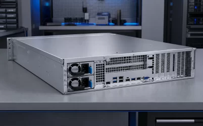
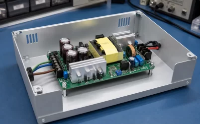
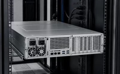
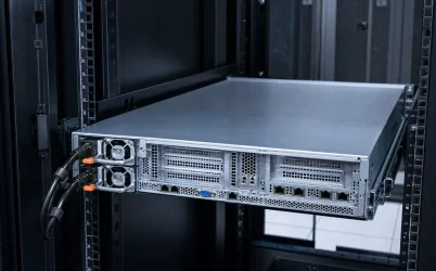
Server PSU connectors are not one universal plug or pinout. The phrase may describe the facility-side power connection, the inlet on a fixed or removable supply, the blind-mate interface between a hot-plug module and its power distribution board (PDB), or a downstream cable feeding the motherboard, processors, accelerators, storage, and fans. Identify that physical boundary first. Then name both mating assemblies, the exact host and PSU revisions, and the document defining the interface. A connector that looks or fits the same may still differ electrically, thermally, or in its control signals.
Quick answer: identify the boundary before naming the connector
A useful server PSU connector description answers five questions: Where is the connection in the source-to-load path? What components mate there? Is it a cabled, card-edge, board-to-board, or busbar interface? Which power and signal functions pass through it? Which model-specific document defines those functions? Connector family identifies the physical component category; it does not establish the pinout, current allocation, control behavior, or host compatibility. If any of those facts remain unresolved, record them as unknown rather than borrowing an assignment from a visually similar supply.
One phrase can refer to five different boundaries
The connector chain begins before electricity reaches the PSU and continues after the PSU has completed its main conversion function. A fixed cabled server supply, a proprietary hot-plug module, and a CRPS-based assembly may expose these boundaries in different ways, but the source-to-load method remains useful for all three.
| Boundary | Mating assemblies | Primary role | Common identification error |
|---|---|---|---|
| Rack source to power cord | Rack PDU outlet and cord plug | Delivers the available facility input | Treating plug shape as proof that voltage, phase, current, and circuit capacity are suitable |
| Power cord to PSU | Cord connector and PSU inlet | Brings AC or, in some platforms, DC input to the converter | Calling the inlet the server output connector |
| Removable PSU to PDB | PSU card edge or blade and mating backplane/PDB connector | Carries main output and potentially standby, control, sense, sharing, or management functions | Assuming a similar contact pattern means an identical pinout |
| PDB to system board | PDB header, busbar, board-to-board connector, or harness and motherboard interface | Transfers the main bus and supporting signals into the host | Assuming the PSU module connects directly to every load |
| System distribution to loads | Motherboard, riser, storage backplane, fan board, CPU, GPU, or accelerator branches | Delivers power to defined load zones | Using a familiar cable name as evidence of a universal wire map |
This classification also separates four terms that are often blurred together. A connector family describes a physical component category. A mating pair identifies the two components intended to engage. A pinout assigns electrical functions to individual contacts. A cable assembly adds conductors, terminals, wire sizes, branching, length, and end-to-end mapping. Knowing one does not automatically establish the other three.
The input connection begins with the rack power source
For an AC-fed server, the input route normally includes a rack PDU receptacle, a detachable cord, and an inlet associated with each installed PSU. In a redundant server, separate cords may connect the modules to different rack feeds, although independent connectors alone do not prove that the upstream failure domains are independent. The connector record should therefore distinguish the rack outlet from the PSU inlet and preserve the approved cord configuration between them.
A DC-input server changes this boundary. Its module or chassis may receive power from a site DC distribution system through an application-specific connector or termination arrangement. A mechanically convenient adapter cannot resolve an unsuitable source voltage, conductor rating, polarity convention, protective device, grounding method, or host approval. Those are properties of the complete input interface rather than the shell alone.
Record input-side evidence without extending it beyond its purpose. The rack PDU documentation defines the source receptacle and electrical service. The cord assembly documentation defines both ends and its applicable rating. The PSU or server documentation defines the accepted input and inlet. A photograph may help identify a candidate connector family, but it does not establish the electrical service behind the receptacle.
The hot-plug module meets the PDB at a mixed-function interface
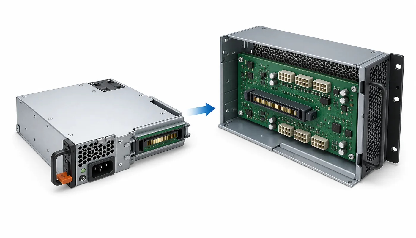
The most distinctive server PSU connector is often the blind-mate boundary at the inner end of a removable module. As the supply slides into its bay, guides and stops align its contact area with a connector on the PDB or power backplane. This arrangement supports service from the chassis exterior without requiring a technician to detach an internal output harness.
Card-edge power connectors are a manufacturer-defined component category, not a universal server wiring standard. A server implementation can combine high-current output and return contacts with smaller contacts for functions such as standby power, module presence, enable control, output status, current sharing, remote sense, or digital management. The functions actually present—and their electrical definitions—depend on the PSU, PDB, and platform design.
The mating PDB is therefore part of the connector identity. It determines where the module output enters the common bus, how source paths are isolated, and how power and signals continue into the host. In a redundant assembly, the board may also coordinate functions that cannot be inferred from the module contact pattern. Powernexu’s explanation of the 1+1 CRPS power distribution board boundary covers how this interface participates in current paths, standby functions, management, and fault isolation.
Physical engagement establishes only that two parts can occupy the same mating position. It does not establish compatible output rails, contact allocation, signal voltage domains, start sequencing, current-share behavior, communication addressing, or firmware support. Those facts require model- and platform-specific evidence.
Downstream connector names describe destinations, not definitions
After the PDB combines or routes the PSU output, the server can distribute power through copper planes, busbars, board-to-board interfaces, or detachable harnesses. The main board may receive one concentrated bus and generate lower-voltage rails near the processors and memory. Other branches can feed storage backplanes, fan boards, PCIe risers, accelerators, or auxiliary controllers.
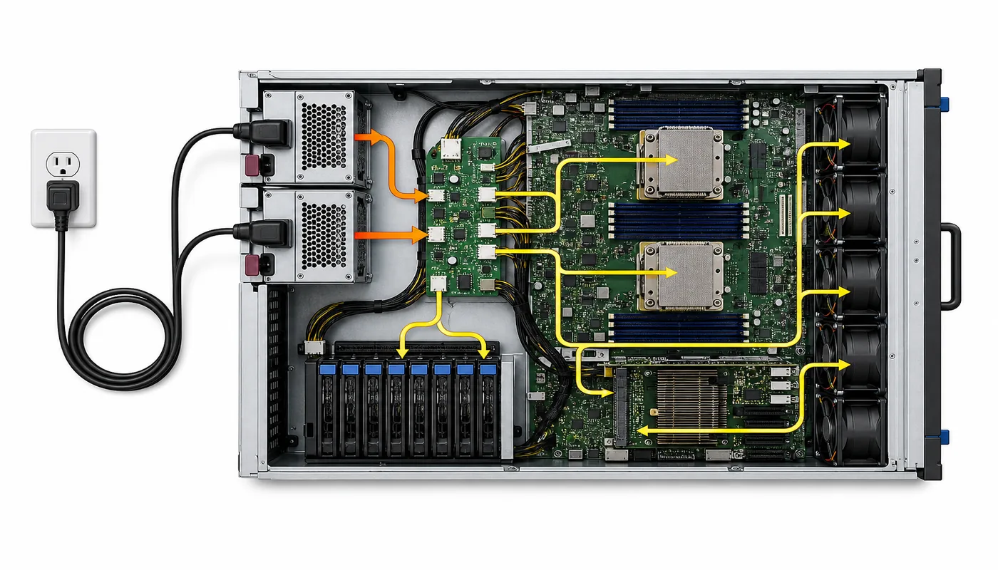
Terms such as “motherboard power,” “CPU power,” “GPU cable,” and “storage power” identify destinations. They do not, by themselves, specify the source-side connector, contact map, conductor size, terminal system, or supported current. A connector shell familiar from desktop hardware may appear in a server assembly while the server vendor uses a platform-specific wiring arrangement. The same caution applies to detachable cables on modular fixed PSUs: the load-side connector may look familiar while the PSU-side port remains specific to one manufacturer or product family.
A busbar connection needs its own identity as well. The absence of a conventional wire harness does not eliminate the interface. The schedule should name the bolted, blade, or board-level joint, its mating surfaces, the assembly drawing that controls it, and the load zone it serves. This prevents a drawing from jumping directly from “PDB” to “GPU” while hiding an intermediate riser or distribution board.
A connector schedule turns the power path into an inventory
A connector schedule is an interface inventory, not a universal wiring diagram. Create one row for every separable or mated boundary in the source-to-load path.
- Assign a stable boundary ID.
- Name both mating assemblies, including exact parts and revisions where known.
- Record the physical class, installed orientation, source side, and load side.
- List only documented power and signal roles; leave unsupported contact functions unresolved.
- Cite the controlling specification, drawing, or cable map and mark each fact as documented, observed, inferred, or unresolved.
This schedule can support architecture and replacement records before every contact is disclosed. A custom PDB or adapter requires additional model-specific assignments, ratings, sequencing, and control behavior; unresolved required functions remain design blockers.
Use each document only for the claim it can support
The host platform specification or service documentation is usually the strongest source for supported module identities and system-level connections. An Intel server system technical product specification illustrates the type of platform-specific primary document engineers should seek. Its authority applies to the identified platform and revision; it should not be converted into a generic pin map for unrelated servers.
A PSU datasheet can define the module’s electrical and mechanical behavior, but it may not identify every host that supports it. A PDB schematic or assembly drawing can show how the mating side routes power and signals. A cable drawing should establish connector part identities, conductor mapping, wire construction, and branch destinations. Connector-manufacturer data defines the component itself—such as mating geometry, material options, and applicable ratings under stated conditions—but does not decide which server signal a system designer assigned to each contact.
Seller photographs and marketplace descriptions belong at the bottom of this evidence hierarchy. They can help locate a model label or identify whether a listing contains a module, cable, or complete assembly. They should not authorize energization, substitution, or adapter construction.
When contact-level interpretation becomes necessary, use a separate evidence-controlled process. The Powernexu article on how to read and verify a server PSU pinout addresses orientation, contact numbering, source quality, measurements, and unresolved functions. Keeping that task separate allows the connector schedule to remain an interface inventory rather than an apparently complete pinout assembled from partial clues.
Mechanical mating closes only one layer of the interface
Visual inspection can establish valuable facts: connector location, approximate family, keying, installed orientation, module guides, insertion direction, and whether contacts appear to be power or signal scale. It can also expose obvious conflicts such as different key positions or an incompatible latch. These observations narrow the search, but they do not prove electrical equivalence.
Several unresolved details can remain after two connectors physically mate:
- Main output and return contacts may occupy different positions or use different parallel-contact groupings.
- A standby or control contact may use a voltage domain that is incompatible with the candidate host.
- Enable, present, status, share, and sense functions may differ or may not exist on both products.
- Digital management may use compatible-looking lines while requiring different addressing, command support, or host firmware behavior.
- Contact sequencing during insertion may depend on staggered geometry that an adapter or substitute does not preserve.
- A familiar cable shell may contain terminals, conductor sizes, or branch mappings unsuitable for the intended load.
These are different failure mechanisms. One mismatch may prevent startup; another may create incorrect status reporting; another may concentrate current in too few contacts; and another may disturb the bus during insertion. Because the consequences differ, “the connector fits” is not a meaningful final status. The schedule should say exactly which mechanical facts are known and which electrical or control facts remain open.
The required evidence depends on what the connector map will authorize
Match the evidence depth to the action the map will authorize:
- Approved PSU replacement: exact host, supported part or supersession, revision, and pairing conditions.
- Harness replacement: assembly identity, both endpoints, conductor and terminal specification, and end-to-end map.
- Mating-connector sourcing: manufacturer part and mate, drawing, orientation, and applicable ratings.
- Custom PDB or adapter: verified assignments, electrical levels, current paths, sequencing, controls, protection, and management behavior.
- Troubleshooting: platform power-path documentation, expected system state, and authorized measurement points.
An explicit unknown is safer than evidence borrowed from a similar connector. If the proposed action depends on that unknown, stop until a controlling source resolves it.
The map is complete when no power boundary is anonymous
A strong server PSU connector map can trace the source from the rack outlet to the PSU inlet, across the removable module interface, through the PDB, and onward to every important motherboard or load branch. Each boundary has two named mating assemblies, a physical connector class, a documented role, a controlling source, and an honest evidence status.
That inventory does not need to publish a universal pinout—because no universal server PSU pinout can safely represent proprietary, cabled, hot-plug, and CRPS implementations. Its value is precision: the phrase “server PSU connector” becomes a specific interface in a specific platform. Once the boundary is named, engineers can obtain the right component drawing, platform specification, cable map, or contact-level evidence without mistaking physical resemblance for electrical interchangeability.