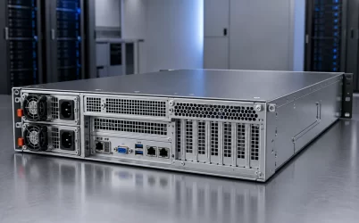
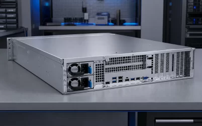
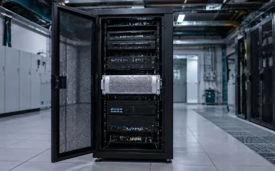
Server power supply voltage must be matched at the input, not inferred from the PSU’s internal DC output. Start with the rack’s nominal AC supply—such as 120V, 208V, or 240V—then confirm that the exact PSU and server configuration accept that voltage and frequency. Next, determine whether available output power, input current, or efficiency changes across the documented input range. The selected condition must also agree with the branch circuit, rack PDU, outlet, cord set, and redundant-feed design. A voltage printed on a marketplace listing is not enough to establish deployability.
Quick answer: match the nameplate to the complete rack power path
A server can use 120V, 208V, or 240V only when its exact PSU input specification and host documentation support the site’s actual supply condition. Higher voltage generally means lower input current for the same delivered power, but it does not automatically provide more PSU output or better efficiency. Those results are model-specific. Record the accepted input range, frequency, maximum input current, conditional output rating, cord and PDU requirements, and the behavior of each redundant feed before assigning the server to a rack.
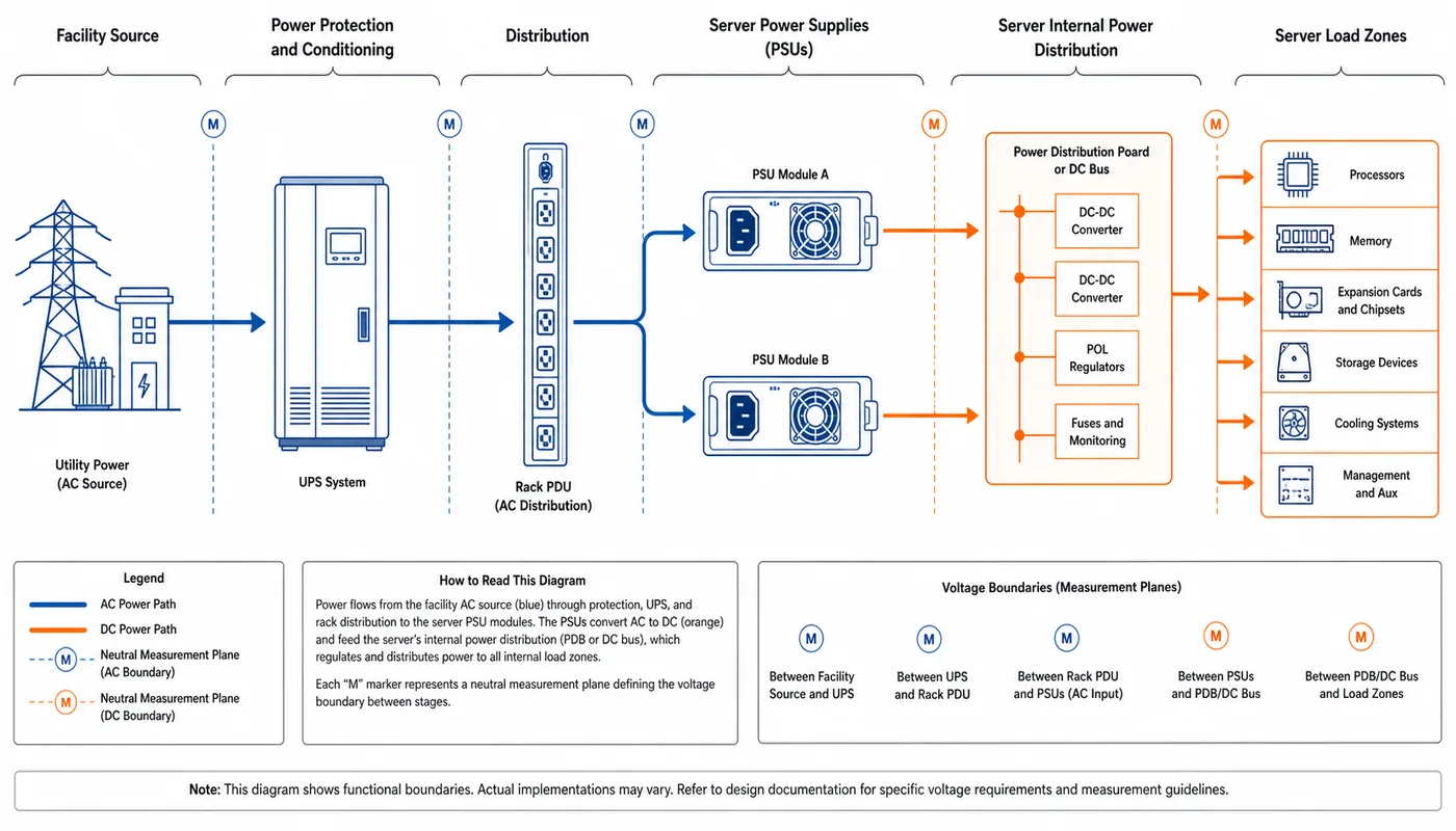
Start with the rack outlet, not the internal DC rail
The phrase “server power supply voltage” can refer to several electrically separate quantities. Confusing them can produce a server that appears compatible on paper but cannot be connected safely or cannot deliver its expected capacity at the deployment site.
- Facility source: the nominal AC or DC service available in the building or data hall.
- PSU input: the voltage and frequency range the exact power module is documented to accept.
- Server distribution bus: the regulated DC output delivered by the PSU to a power distribution board, motherboard, or busbar.
- Point-of-load rails: the lower voltages produced near processors, memory, storage, and other electronic loads.
This article focuses on the facility-to-PSU interface. The PSU may produce a 12 V-class bus or another platform-specific distribution voltage internally, but that output does not tell an installer whether the rack connection should be 120V, 208V, or 240V. A server with a nominal 12V internal bus can still require high-line AC at its PSU input.
There is also an important distinction between a conventional AC-input module and a PSU designed to accept facility DC. The connector, protection, grounding, and supported host may differ even if both ultimately supply a similar internal bus. Powernexu’s discussion of server DC power supply voltage boundaries covers that separate architecture in more depth.
Read the PSU nameplate as a conditional operating envelope
The PSU label is the first source for electrical identity, but it should be reconciled with the server manufacturer’s installation and configuration documentation. A power module may have a broad electrical input capability while the host platform imposes additional restrictions on supported PSU combinations, available output, firmware, or configured components.
Capture the exact module model and revision before interpreting the electrical fields. Similar-looking modules from the same wattage class can have different input ranges, connector definitions, cooling behavior, or host support. The relevant nameplate and documentation fields normally include the following, when provided:
| Field | What it establishes | What it does not establish |
|---|---|---|
| Accepted input range | Whether the PSU can operate from the documented source voltage | Whether the full advertised output is available throughout that range |
| Input frequency | Supported AC frequency conditions | Compatibility with a particular outlet, cord, or PDU |
| Maximum input current | An input-side rating used in electrical planning | The server’s expected current at every workload |
| DC output rating | The documented output envelope under stated conditions | Usable server capacity under every input, temperature, or redundancy state |
| Model and revision | The identity to reconcile with platform documentation | Interchangeability based solely on a similar enclosure |
Look for footnotes and separate rating rows. Some server PSUs provide different output capability at different input conditions. Others retain the same nominal output but show different current or efficiency data. Neither behavior should be generalized across server power supplies. If the documentation states a reduced output at low-line input, size the server configuration from that lower supported value rather than the larger headline wattage.
The host documentation may also define which power modules can be paired, whether mixed ratings are supported, and which input condition is required for a particular server configuration. This document-first method is consistent with IBM’s guidance for determining equipment power requirements from the specific system and installation conditions.
120V, 208V, and 240V change the rack math
For the same DC workload, a higher AC input voltage generally reduces the line current required by the PSU. This can make 208V or 240V attractive where rack power density or branch-current capacity is constrained. It does not mean that every server should be moved to the highest available voltage. The exact PSU range, building distribution, receptacles, service practices, and alternate operating locations still control the decision.
| Planning question | 120V | 208V | 240V |
|---|---|---|---|
| Can the PSU accept it? | Only if the documented range covers the actual source condition | Only if the documented range covers the actual source condition | Only if the documented range covers the actual source condition |
| Current for the same delivered power | Higher than at 208V or 240V, assuming comparable efficiency and power factor | Lower than at 120V; higher than at 240V under the same assumptions | Lower than at 120V or 208V under the same assumptions |
| Available PSU output | May be reduced on some models | Model-specific | Model-specific |
| Infrastructure fit | May align with office, lab, edge, or existing low-line circuits | Often used in rack environments where the facility provides it | Useful where compatible high-line distribution and service locations are available |
| Efficiency implication | Use the exact model’s data at the expected load | Use the exact model’s data at the expected load | Use the exact model’s data at the expected load |
A simple calculation illustrates the current difference. For a hypothetical PSU delivering 1,000W DC at 92% efficiency and a power factor of 0.98, approximate single-phase input current is:
Input current ≈ DC output ÷ (input voltage × efficiency × power factor)
- At 120V: approximately 9.24A
- At 208V: approximately 5.33A
- At 240V: approximately 4.62A
These figures are explanatory examples, not branch-circuit sizing values. Actual planning must use the PSU’s documented maximum input current, the complete server configuration, redundancy mode, applicable electrical requirements, and the facility’s design policy. A three-phase rack PDU also requires upstream calculations appropriate to its own topology, even when each connected PSU receives a line-to-line or line-to-neutral single-phase supply.
Lower current can reduce stress on current-limited distribution components and may reduce resistive losses in a given path. However, a voltage change does not guarantee a particular energy saving. Conversion efficiency depends on the exact PSU, input condition, load percentage, temperature, and redundancy policy. Compare model-specific curves rather than assuming that every high-line condition produces the same benefit; the server PSU efficiency operating-point method explains how to make that comparison.
The selected voltage propagates into cords, PDUs, and redundancy
Once a voltage is selected, it becomes an attribute of the complete rack connection. The PSU inlet, cord set, rack PDU outlet, PDU input, upstream branch circuit, and service procedure must all agree. An adapter that merely makes two connectors mate does not demonstrate correct voltage, current capacity, grounding, retention, temperature suitability, or platform support.
A practical deployment review can follow this sequence:
- Identify the exact powered configuration. Record the server model, installed CPUs, accelerators, memory, storage, expansion devices, fans, and approved PSU modules.
- Extract the input conditions. Record the accepted voltage range, frequency, maximum input current, and any input-dependent output rating from the PSU and host documentation.
- Characterize the rack source. Document the nominal voltage, expected operating tolerance, phase relationship where relevant, rack PDU model, outlet type, and upstream branch assignment.
- Match the cord as an electrical component. Both connector ends, voltage and current ratings, conductor capacity, length, retention, and applicable installation requirements must suit the connection.
- Evaluate the degraded state. Determine what one branch and one PSU must carry after the other input path or module is unavailable.
- Repeat the review for nonproduction locations. Staging benches, repair areas, disaster-recovery sites, and temporary racks need a compatible source rather than an assumed one.
Redundant PSUs introduce a particularly important current condition. During normal operation, two modules may share the server load according to the platform’s control policy. If one module or input feed is lost, the remaining path may have to supply the full permitted server demand. Branch and PDU planning should therefore account for the required fault state rather than relying on an assumed 50/50 normal split.
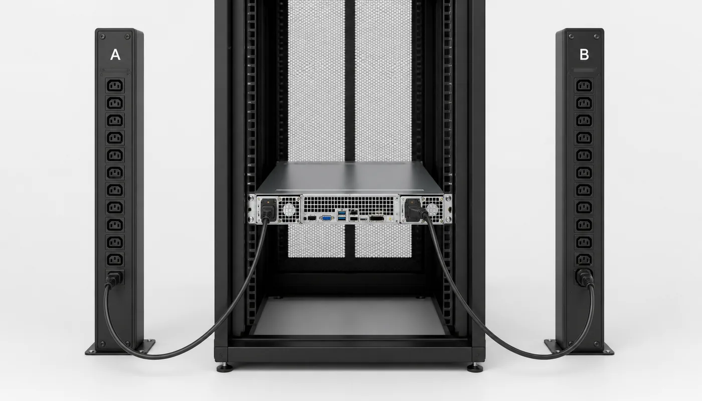
Two PSU cords also do not create feed redundancy merely because they terminate in different outlets. If both outlets belong to the same PDU, branch circuit, upstream protective device, or maintenance domain, that shared element can remove both inputs. Where the availability design calls for independent A/B feeds, each path should remain electrically compatible with the PSU while preserving the intended separation from rack outlet to the defined upstream failure boundary.
Production, staging, and recovery must preserve the voltage assumption
A server selected for high-line operation may work correctly in its production rack yet become unusable during staging or recovery if those locations provide only an unsupported source. This issue is most visible with high-line-only PSUs, but it can also affect universal-input modules when available output, cord inventory, or host policy changes with the operating condition.
Record the voltage boundary in the asset and spare records rather than leaving it only in the rack drawing. A replacement PSU should be checked against the same input and conditional-output evidence as the installed module. Matching wattage and enclosure shape does not show that the spare will deliver the required power from the available source.
Maintenance procedures also need to preserve the live path. Before moving or replacing a server, operations should know which cord reaches feed A, which reaches feed B, what voltage each feed supplies, and whether the destination rack supports the same arrangement. If a temporary PDU or extension changes the outlet or source, treat that change as an electrical design review rather than routine cable management.
A one-page voltage record prevents deployment surprises
The most useful output of a server voltage review is a compact record that can follow the platform through installation, service, and relocation. It should contain:
- server model and approved hardware configuration;
- exact PSU manufacturer, model, revision, and quantity;
- documented input voltage and frequency range;
- available output and other limits at the selected input condition;
- maximum documented input current relevant to electrical planning;
- rack source voltage, PDU, outlet, and branch assignment;
- approved cord identity and connector types at both ends;
- A/B feed relationship and the required surviving operating state;
- compatible staging, maintenance, and recovery locations; and
- source documents and revision dates supporting the decision.
This record separates three questions that are often compressed into one: whether the PSU can energize from the source, whether it can deliver the required server output under that condition, and whether the rack infrastructure can support it through normal and degraded operation. A successful server power supply voltage decision closes all three. The result is not a universal preference for 120V, 208V, or 240V, but a documented match between the exact PSU nameplate, the configured host, and every rack location expected to power it.