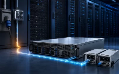
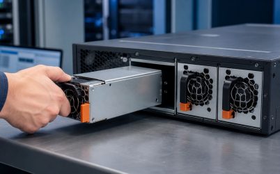
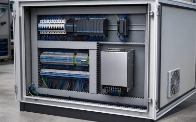
A server DC power supply can mean two different things: a module that accepts DC from the facility, or the regulated DC source inside an ordinary AC-fed server. The distinction changes the connector, protection, conversion stages, grounding, and compatible host platform. For a conventional rack server, the PSU typically converts AC into a 12 V-class main bus before point-of-load regulators create the processor and memory rails. In telecom and some data-center installations, a DC-input module instead accepts a site DC bus and converts or regulates it for the server. The practical task is to identify both sides of the module—its incoming DC envelope and the bus the server expects—before treating “DC power supply” as a useful specification.
The phrase has an input side and an output side
Every server PSU produces DC for electronic loads, but that does not make every server PSU a DC-input product. An AC-input PSU includes rectification, power-factor-correction behavior, isolation, and downstream conversion appropriate to its documented mains range. A DC-input module begins from a defined direct-current source and uses a different front end. Some products are designed for a nominal telecom battery plant; others belong to a rack power shelf or a proprietary high-voltage DC system. The permitted range, polarity, grounding arrangement, connector, and protective devices are model-specific.
The output description is a separate question. A module may feed a 12 V-class server bus, a 48 V-class distribution bus, or another platform-defined voltage. Board-level converters then create the much lower voltages used by processors, memory, storage, fans, and accelerators. “48 V input” therefore does not prove “48 V output,” while “48 V server architecture” does not reveal whether the rack delivered AC or DC to the first conversion stage.
| Question | What it establishes | What it does not establish |
|---|---|---|
| What DC source enters the module? | Input range, polarity, connector, source behavior, and protection basis | The server-side bus or host compatibility |
| What bus leaves the module? | PDB voltage domain and downstream conversion arrangement | Facility input architecture |
| Which host supports the module? | Mechanical, electrical, control, cooling, and firmware fit | Compatibility with another server using the same nominal voltage |
A 12 V bus and a 48 V bus distribute current differently
For the same power, raising distribution voltage reduces current. The relationship is simply current equals power divided by voltage. A hypothetical 2,400 W load would draw 200 A from a 12 V bus before accounting for conversion loss, but 50 A from a 48 V bus at the same boundary. This comparison is not a product rating; it illustrates why conductors, busbars, connector contacts, copper area, and distribution loss become increasingly difficult at low voltage as server density rises.
A 12 V-class architecture keeps a familiar main bus close to motherboard and peripheral loads. It can be an effective fit for conventional rack servers where path lengths and total power remain manageable. A higher-voltage bus reduces current through the longer or more concentrated distribution path, but it moves conversion responsibility downstream. Local intermediate converters may create 12 V or feed voltage-regulator stages closer to the load. That adds packaging, control, transient, and cooling work near compute hardware while easing the upstream copper burden.
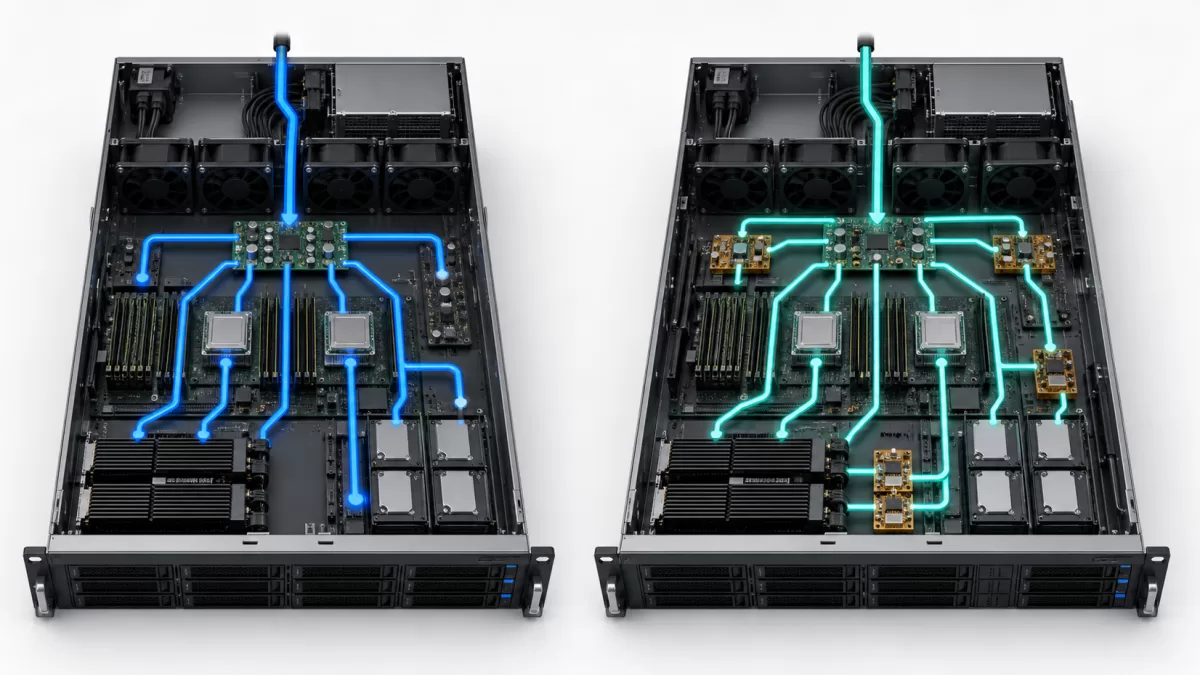
The relevant comparison is therefore not “12 V versus 48 V” in isolation. It is where conversion occurs, how far each voltage travels, which current path experiences the largest step load, and whether the platform provides space and cooling for localized converters. The server architecture article on conversion stages and distribution paths provides the broader AC-to-load context; the DC-focused question here is where the voltage-domain boundary is placed.
DC input changes the facility-to-server boundary
A DC-fed server can connect more directly to a battery-backed rectifier plant or another documented DC distribution system. Removing an unnecessary AC inversion stage may be attractive in a facility designed around DC, but the server input is not a raw pair of interchangeable wires. Source voltage moves with plant operating state, charging conditions, battery discharge, cable drop, and fault isolation. The PSU must support the entire specified source envelope, not merely its nominal value.
Polarity deserves explicit treatment. Telecom conventions, grounded conductors, and connector keying vary by system. Reversing a DC source can create a severe fault if the product and upstream protection are not designed to tolerate it. Documentation should state conductor identification, permitted grounding, protective-earth connection, branch protection, disconnect method, and the exact mating hardware. None of those details can be inferred safely from a nominal voltage.
DC interruption also behaves differently from AC interruption. Alternating current crosses zero every cycle; direct current does not. Switches, breakers, fuses, contactors, and connectors must be rated for the actual DC voltage, prospective fault current, and operating environment. A device with a suitable-looking AC current marking is not automatically suitable for interrupting the same current on DC. The rack branch and service procedure must use components whose DC ratings and polarity rules match the installation.
The front end still performs more than voltage conversion
A DC-input module may need input filtering, surge and transient control, inrush limiting, isolation where the design requires it, switching conversion, output regulation, fault containment, and housekeeping power. The exact topology is product-specific, but each function has a system consequence. Inrush affects the branch source and connector during insertion. Input filtering interacts with the source impedance and conducted-noise environment. Isolation and grounding influence accessible circuits, fault paths, and compliance. Output control determines how the module joins an energized shared bus.
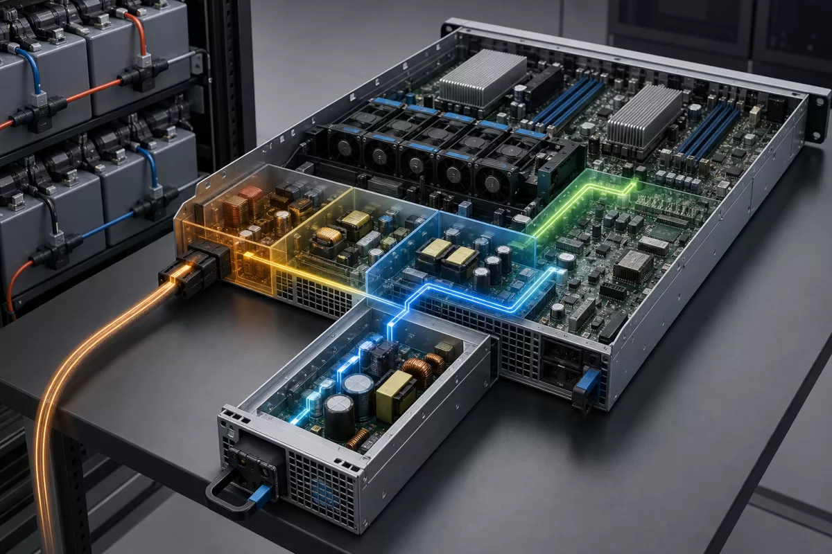
Redundant DC modules also need coordinated ORing or equivalent reverse-current blocking, current sharing, fault isolation, and controlled startup. Those functions keep one module from back-feeding a failed partner and help an inserted supply join the bus without disturbing the running load. The underlying redundancy principles are covered separately in server power-supply redundancy design; for a DC-input purchase, the additional issue is whether each branch comes from a genuinely independent DC source and protective path.
The load sees a chain of dynamic converters
Modern processors and accelerators can change demand faster than a distant facility source can respond. Energy storage and control loops are distributed across the PSU output, PDB, intermediate bus converters, motherboard capacitors, and point-of-load regulators. A stable nominal DC input does not by itself guarantee acceptable behavior at the processor rail. Conversely, a well-designed downstream network can buffer short events without demanding that every transient propagate unchanged back to the rack bus.
The design boundary should specify which stage must handle each time scale. The PSU data may define output regulation and transient behavior at its own terminals. The PDB contributes resistance and inductance. Local converters have their own control bandwidth and protection thresholds. Firmware may cap or sequence loads. For high-density accelerators, the useful evidence is a voltage response observed at the relevant bus during representative workload transitions, together with telemetry that shows whether modules approach current, temperature, or input limits.
This layered view prevents a common sourcing error: substituting a module because its steady output voltage and power appear similar. Two supplies can differ in startup timing, current-share behavior, standby output, presence detection, management commands, fault signaling, or transient response. Those differences may leave the server unable to boot, report health, share load, or remain stable even when the primary DC voltage is correct.
Mechanical and control identity closes compatibility
A replacement must match more than voltage. The mechanical envelope, insertion depth, latch, keying, airflow direction, fan behavior, blind-mate position, output contacts, control pins, standby supply, and communication interface all belong to the host contract. Even supplies derived from a common modular form factor can use different supported ratings, firmware expectations, or connector definitions. Adapters that expose a convenient DC terminal do not establish server compatibility or safe hot-plug operation.
For a new platform, write the interface as two connected specifications. The source-side specification describes DC range, polarity, grounding, branch protection, connector, cable drop, transient environment, and feed independence. The server-side specification describes the PDB interface, main and standby outputs, management behavior, cooling, module count, fault isolation, and supported operating states. Procurement can then compare actual modules against a bounded interface rather than searching by a phrase that spans several architectures.
Use the installation to resolve which DC supply you need
A conventional enterprise server on an AC rack PDU usually needs its supported AC-input module, even though that module produces DC internally. A telecom room with a battery-backed DC plant needs a host-approved DC-input option whose full source range, polarity, protection, and connector match that plant. A dense compute rack built around a 48 V-class bus needs the corresponding shelf, busbar, intermediate conversion, protection, and server hardware as one coordinated architecture; replacing only the PSU does not convert a 12 V platform into a higher-voltage one.
The phrase server DC power supply becomes precise only after four boundaries are named: the facility source, module input, server distribution bus, and load-side conversion. Once those boundaries are visible, the engineering choice is straightforward to describe. Select a documented module for the intended host and DC source, then preserve its protection, grounding, distribution, control, and cooling assumptions through the rack. The valuable result is not “DC” by itself, but a power path whose voltage changes occur in deliberate places and whose interfaces remain supportable.