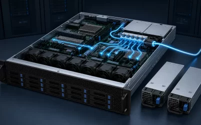
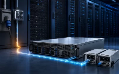
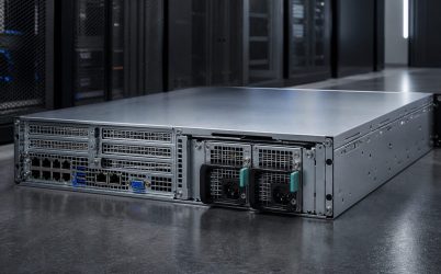
An industrial switching power supply should be selected around the machine’s electrical disturbances, load behavior, enclosure, and required recovery behavior—not merely its nominal voltage and wattage. The useful specification states the permitted input range, continuous and peak DC load, ambient and cooling conditions, protection response, mounting format, and what the machine must do after a fault. A DIN-rail, enclosed, or open-frame unit can all use switch-mode conversion; “industrial” describes the operating duty and integration obligations, not one universal mechanical format.
The switching topology is only the conversion method
A switching power supply regulates its output by transferring energy through semiconductor switches, magnetic components, and filtering stages at a frequency far above the incoming line frequency. Compared with a linear supply, this approach can reduce size and conversion loss, but it also introduces conducted and radiated noise that must be managed in the finished machine.
For an AC-input unit, the functional path commonly includes input protection and filtering, rectification, a high-voltage DC link, a controlled switching stage, isolation where the design provides it, secondary rectification, and a feedback loop. The exact implementation varies. A DC-input industrial converter starts from a DC source and may be isolated or non-isolated. Therefore, “switching” does not establish the input type, isolation rating, output behavior, safety approval, or suitability for a particular machine.
The industrial question is broader: can the chosen supply maintain an acceptable DC bus while the factory source and connected loads behave as they actually do? Powernexu’s discussion of the industrial AC-DC power path provides more detail on the mains-to-load boundary; this article focuses on translating the operating environment into a switching-supply requirement.
Map the disturbances on both sides of the converter
Factory power is not an ideal sine wave at a fixed amplitude. Contactors, variable-frequency drives, welders, large motors, and upstream switching can create dips, interruptions, surges, and common-mode noise. The supply datasheet must be read for the specific input, load, and environmental condition rather than treated as a universal immunity certificate.
Start by separating four events that are often collapsed into “dirty power.” A sustained low-line condition challenges available output power and input current. A brief voltage dip tests stored energy and hold-up behavior. A high-energy surge is primarily a protection-coordination problem. High-frequency noise is an EMC and grounding problem. One feature cannot substitute for all four.
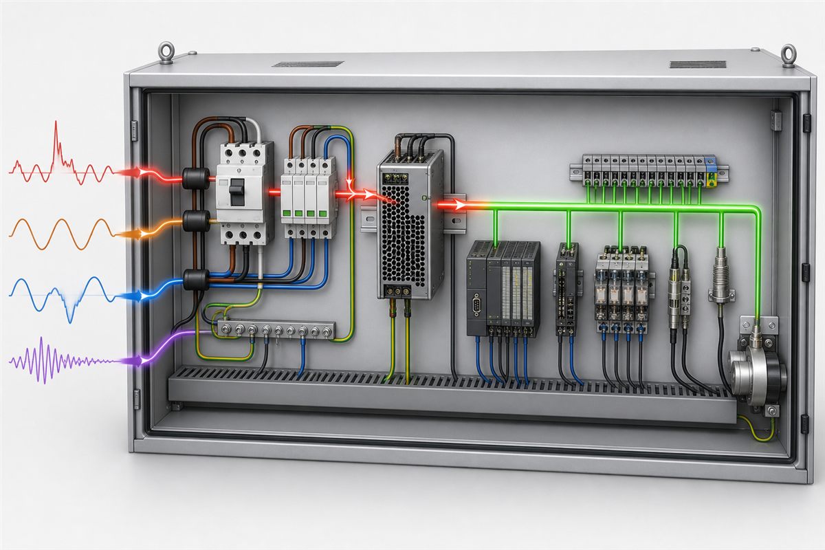
The output side can be equally demanding. PLC electronics draw a relatively stable current, while relay coils, solenoids, brakes, heaters, capacitive input filters, and DC motors may create starting pulses or regenerative energy. A supply with adequate average wattage may still enter current limit during a coordinated machine start. Conversely, oversizing by a large factor can leave the supply operating inefficiently and may increase available fault energy in branch wiring.
Create a time-based load profile: steady operating current, simultaneous startup current, pulse duration, repetition rate, and any energy returned toward the DC bus. Then compare that profile with the manufacturer’s documented overload curve and current-limit mode. “150% peak” is incomplete unless its duration, thermal conditions, and recovery behavior are stated.
Translate the cabinet into an operating envelope
A nameplate ambient limit does not describe the temperature beside a power supply inside a closed control panel. Heat from drives, contactors, transformers, and neighboring supplies creates local hot zones. The relevant temperature is the one defined by the manufacturer—often measured at a specified point around the unit—not the room temperature outside the enclosure.
Derating curves connect that local temperature to usable output. Some supplies also derate at low input voltage, high altitude, or an installation orientation that restricts convection. These effects can overlap. If a unit is expected to deliver full output at low line in a hot cabinet, confirm that the published curves support that combined condition instead of reading each limit independently.
Mechanical format transfers different responsibilities to the system integrator:
| Format | Integration advantage | Responsibility that remains with the machine |
|---|---|---|
| DIN rail | Fast panel mounting and orderly terminal access | Rail spacing, convection clearance, touch protection, and cabinet thermal design |
| Enclosed chassis | Metal cover provides mechanical protection around the converter | Protective-earth bonding, mounting, wiring protection, and airflow |
| Open frame | Flexible integration and potentially compact packaging | Enclosure, accessibility control, spacing, cooling, grounding, and final-equipment compliance |
Open-frame integration is a separate engineering territory because the host equipment supplies much of the mechanical and safety context. The open-frame switching power supply integration guide covers those enclosure-level duties without assuming they apply identically to enclosed or DIN-rail products.
Protection behavior must match the machine’s fault physics
Protection acronyms describe monitored conditions, not the complete machine response. Overvoltage protection can shut down or clamp the output depending on the design. Overcurrent protection may use constant-current limiting, foldback, hiccup restart, or shutdown that requires a reset. Overtemperature protection may reduce output or stop conversion. Short-circuit protection does not guarantee that every branch conductor or load is protected.
Consider a jammed actuator on a shared 24 V bus. With constant-current limiting, the faulted branch may pull the bus below the PLC’s acceptable input. Hiccup operation can make the entire machine repeatedly restart. A latched shutdown can produce a clean stop but require intervention. None is universally superior; the desired response follows from the machine’s safe-state strategy and branch protection.
Selective coordination is therefore a DC distribution problem. Branch fuses or electronic circuit protectors should isolate a fault before it collapses unrelated controls when continuity is required. Their time-current or electronic trip behavior has to coordinate with the supply’s current limit. Simply adding branch devices without comparing those curves can still allow the supply to enter protection first.
Grounding and EMC are properties of the installation
A compliant power supply can be installed in a machine that fails emissions or immunity tests. Cable length, loop area, protective-earth impedance, shield termination, panel bonding, filter placement, and proximity to motor leads change the finished system. Input and output conductors should not be routed as a single noise-coupled bundle merely because they terminate near the supply.
Protective earth serves safety and high-frequency current-return functions, while the DC output may be floating or intentionally bonded according to the system design. Those are different decisions. Bonding DC negative to earth can improve reference stability in one machine and create an unwanted ground loop in another. Follow the supply documentation and the applicable final-equipment requirements rather than assuming a universal grounding arrangement.
Likewise, an external line filter is not a drop-in cure. Its effectiveness depends on source and load impedance, grounding, wiring placement, and leakage-current constraints. Evaluate EMC with the representative enclosure, cable set, load states, and switching devices operating.
Continuity may require more than a larger supply
If loss of the DC bus causes unsafe motion, damaged work, or an expensive restart, extra wattage does not create availability. The architecture may require redundant supplies, a redundancy or ORing module, an uninterruptible DC buffer, separate supply zones, or a deliberate combination of these measures.
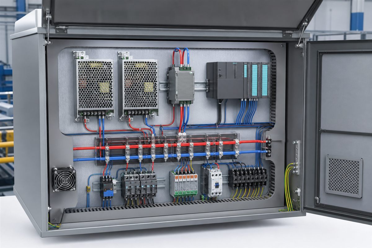
Parallel-capable supplies need documented current-sharing behavior when both are expected to carry load. Redundancy also needs surviving capacity: after one source or module is lost, the remaining path must support the defined load under its actual thermal and input conditions. Two supplies connected to one upstream breaker do not protect against loss of that breaker. Two output paths joined without suitable isolation can allow one failed unit to pull down the bus.
A buffer or DC UPS solves a different problem. It bridges a source interruption for a stated time, allowing continued operation or an orderly shutdown. Stored-energy capacity, battery or capacitor condition, charge current, environmental temperature, and end-of-life behavior belong in that design. The correct architecture follows the required continuity interval and the failure domains that must be tolerated.
Specify behavior at transitions, not just at steady state
A machine exposes its power system during startup, stop, brownout, emergency-off, fault clearing, and power restoration. Define the required sequence for each transition. If multiple supplies create several DC rails, uncontrolled rise and fall timing can back-power interfaces or cause controllers and actuators to disagree about machine state.
Remote sensing, where supported, can compensate for wiring drop at the intended sense point, but it cannot correct an undersized conductor or poor terminal. Output-voltage adjustment can recover a planned distribution drop, yet raising the source voltage also raises voltage at lightly loaded branches. Both features require limits derived from the loads, wire lengths, and protection arrangement.
For a new design, capture representative waveforms at the supply input, DC bus, and a sensitive load during the events that matter. The purpose is not to claim a universal pass/fail number; it is to determine whether the installed system stays within the load’s permitted voltage-time envelope and recovers without an unsafe cycle.
The purchase specification should describe a machine state
A defensible request for an industrial switching power supply is concise but conditional. It identifies the source, regulated output, load profile, local ambient range, mounting orientation, cooling method, cabinet spacing, required approvals for the end market, EMC environment, protection response, continuity objective, and the signals or alarms the controller will use. It also distinguishes mandatory conditions from preferences.
That document turns a vague product search into an engineering comparison. One candidate may be attractive for narrow DIN-rail width, another for short-term overload behavior, and another for parallel operation or harsh-environment options. The winning supply is the one whose published operating envelope contains the machine’s real states—and whose fault behavior supports the machine’s intended safe response.