A high-efficiency server power supply minimizes conversion loss across the server’s real operating range while preserving regulation, transient response, thermal limits, and redundancy. The efficiency badge is useful evidence at defined test points, but it does not identify where losses occur or predict every installed operating state. The strongest design combines an efficient AC-DC topology, low-loss output rectification, sensible bus voltage, right-sized modules, and redundancy control that avoids keeping multiple supplies in an inefficient light-load region.
High efficiency is the result of a loss budget
Efficiency is DC output power divided by AC input power under stated conditions. The difference becomes heat inside the power supply. For a hypothetical operating point delivering 1,000 W at 94% efficiency, AC input is approximately 1,064 W and conversion loss is about 64 W. At 96%, input is approximately 1,042 W and loss is about 42 W. The efficiency change is two percentage points, but the internal heat falls by roughly 22 W at that operating point.
That heat reduction can lower PSU fan demand, reduce the thermal load handed to the rack, and create more thermal margin within a dense chassis. It does not automatically produce a corresponding facility-level saving because upstream conversion and cooling behavior also matter. Still, watts of loss are often more useful than percentage points: they reveal what the chassis must remove and allow alternatives to be compared at the same delivered load.
A high-efficiency design is not one component. Conduction loss rises with resistance and current; switching loss depends on device transitions, frequency, voltage, and circuit conditions; magnetic components have copper and core losses; capacitors have ripple-current loss; control electronics and fans consume power even when server load is low. The design task is to reduce the combined loss without compromising the electrical operating envelope.
The AC front end establishes the first efficiency boundary
In an AC-input server PSU, the input filter suppresses conducted noise but contributes resistance. Rectification creates conduction loss. An active power-factor-correction stage shapes input current and commonly creates a regulated high-voltage DC link for the isolated conversion stage. Semiconductor choice, magnetic design, switching strategy, and control timing all influence how much power is lost here.
Power factor and efficiency are related but not interchangeable. Power factor describes how effectively current waveform and phase use the AC source; efficiency describes how much input real power reaches the DC output. A supply can have strong power factor yet still dissipate meaningful conversion heat. Procurement requirements should keep the two measurements separate and state their load and input-voltage conditions.
Input voltage also changes current and device operating points. For the same real input power, a lower line voltage requires higher current, which can raise conduction loss in the cord, input path, rectifier, PFC stage, and connectors. The actual curve remains model-specific, so high-line operation should not be assigned a universal savings percentage. Compare manufacturer data at the facility voltages that will actually be used.
Resonant conversion and synchronous rectification attack different losses
After the DC link, the isolated conversion stage transfers energy through high-frequency magnetics. Resonant topologies can arrange voltage or current transitions so power semiconductors switch under lower-stress conditions, reducing switching loss over the range for which the circuit and controls are optimized. The benefit depends on load, input, switching frequency, component tolerances, and the chosen control method; “resonant” alone is not proof of a particular efficiency.
On the low-voltage output, diode forward drop can become expensive at server-level current. Synchronous rectification replaces or supplements diodes with actively controlled MOSFETs to reduce conduction loss when timing and operating conditions are suitable. It adds control complexity: poor timing can create reverse current or switching loss that erodes the intended gain.
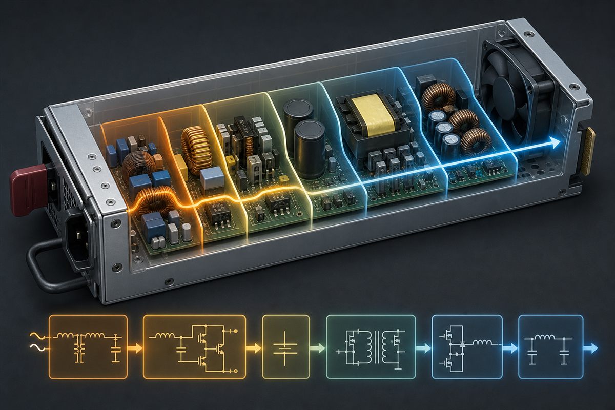
The output filter, busbars, connector contacts, and power distribution board continue the loss budget after conversion. They may sit outside the PSU efficiency measurement boundary even though the server must cool their loss. This boundary explains why two systems using similarly certified modules can differ at the load: connector resistance, copper length, PDB topology, and point-of-load conversion still shape end-to-end performance.
Bus voltage changes where the copper loss appears
For a fixed power transfer, raising distribution voltage reduces current. Because conductor loss follows current squared times resistance, lower current can reduce busbar, cable, connector, and PDB loss or permit a smaller copper cross-section. This is one reason higher-voltage distribution is considered in dense AI and HPC systems.
The gain is not free. A higher-voltage bus moves conversion work closer to CPUs, accelerators, memory, and storage. Additional intermediate or point-of-load stages have their own losses, control interactions, space requirements, and thermal paths. A 48 V or 54 V architecture should therefore be compared as an end-to-end chain, not declared more efficient solely because its distribution current is lower.
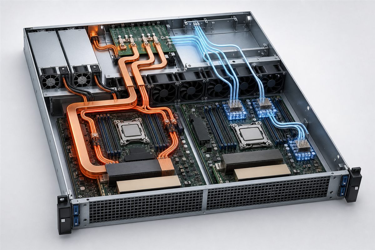
A 12 V bus can remain rational where the server ecosystem, PDB, motherboard, and loads are designed around it and distribution distances are short. A higher-voltage bus becomes more attractive as power and distance make copper loss, connector density, or current handling a dominant constraint. The compatibility boundary includes blind-mate connectors, PDB design, protection, standby power, controls, and downstream converters—not voltage alone.
Fan and standby power dominate a different part of the curve
At high output, semiconductor and magnetic losses dominate. At light load, fixed overhead becomes proportionally important: control bias supplies, telemetry, housekeeping circuits, standby output, and fan operation may remain active while little main-rail power is delivered. This is why an excellent peak efficiency does not establish excellent low-load performance.
Fan control connects electrical and thermal design. A lower-loss converter can need less airflow, yet a smaller high-density module may require a restrictive, high-pressure cooling path. Fan input belongs in the efficiency boundary only if the applicable measurement method includes it, so test reports should be interpreted consistently. Server system fans may also respond to PSU temperature and airflow impedance outside the PSU’s certified result.
Standby deserves explicit treatment in fleets with many powered but inactive nodes. The main converter may be disabled while management, wake functions, and the BMC remain energized. Compare standby consumption under the server states that matter rather than extrapolating from the main-output curve.
Redundancy policy determines each module’s operating point
In a 1+1 arrangement with equal current sharing, a 600 W server load may place approximately 300 W on each active module, ignoring small sharing differences. If one module carried most of the load while the other remained ready, the active unit could operate at 600 W. Those operating points can have different combined losses, even when the hardware is identical.
High-efficiency or cold-redundancy modes may concentrate load on fewer modules and keep another in a standby state. This can improve conversion efficiency at light server load, but it is a platform function rather than a generic PSU feature. The transition must be supported by the server, firmware, PSU controls, and redundancy policy. It also changes runtime distribution between modules and requires enough surviving capacity for a failure or load rise.
At heavier load, balanced sharing can become necessary for capacity and thermal reasons. The control policy should move between states without violating bus regulation or masking a failed module. PMBus telemetry can expose input power, output power, temperature, fan speed, and status where a platform and module support those commands, but capability is model-specific. Powernexu’s server PSU efficiency analysis explains how operating-point data can be converted into a fleet load picture; the architectural point here is that redundancy control actively places modules on that curve.
Certification is evidence, not a complete architecture review
80 PLUS levels provide comparable minimum-efficiency requirements at specified load points, input conditions, and program categories. They are valuable for screening and compliance, but the mark does not replace the certified model record or its test conditions. It also does not by itself establish transient response, ripple, acoustic behavior, hot-swap compatibility, PMBus support, or efficiency between the specified points.
Regulatory requirements may apply to the complete server product in a target market and can use definitions or test procedures that are not identical to a voluntary label. The responsible comparison identifies the exact PSU model, server category, input voltage, redundancy configuration, measurement boundary, and effective regulatory date. Avoid transferring a desktop PSU result or one voltage condition to a server configuration it did not cover.
The dedicated 80 PLUS Titanium server power supply article addresses when that tier’s certified points are economically useful. A mechanism-focused review asks a different question: whether the electrical architecture keeps loss low in the operating states the server will spend time in.
Follow the heat to identify the next design improvement
Once the module meets capacity, compatibility, safety, and transient requirements, the next efficiency improvement should target the largest installed loss. If low-line input raises front-end loss, facility voltage and distribution deserve attention. If internal current is the constraint, bus architecture and copper paths matter. If idle nodes dominate, fixed overhead and redundancy mode may outweigh peak efficiency. If a dense chassis forces high fan power, module power density and airflow impedance become part of the energy problem.
This loss-location method prevents an efficiency tier from becoming a substitute for engineering. A genuinely high-efficiency server power supply is one whose topology, controls, bus interface, cooling, and redundancy behavior keep waste low where the deployed server actually operates—while still preserving the response and compatibility that make the server dependable.