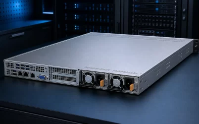
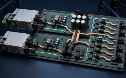
A server switching power supply is a switched-mode power supply (SMPS) designed to convert facility input into the regulated DC power a server platform requires. “Switching” describes the conversion method: semiconductor devices operate at high frequency, magnetic components transfer and reshape energy, and feedback control adjusts each cycle to hold the output within its specified limits. In a server, that conversion is only the first part of the path. The PSU must also cooperate with input filtering, power-factor correction, isolation, a distribution board, load-side voltage regulators, cooling, protection, and management. Following those stages explains what the term means and what must match the host.
The input first becomes a controlled high-voltage energy source
For a typical AC-input server module, mains power does not travel directly to the processor rails. It first passes through protection and electromagnetic-interference filtering intended to limit conducted noise in both directions. A rectification stage then produces a DC link, while an active power-factor-correction stage commonly shapes input current and regulates the intermediate bus. Exact circuits vary by product, input class, and power level.
This front end explains why “auto-ranging” and “full output” are different claims. A PSU may accept more than one nominal mains range, yet its available output, input current, efficiency, or cord requirement can remain conditional. Those limits come from the exact datasheet and server option matrix. The ENERGY STAR Computer Servers test method specifies controlled input voltage, frequency, and waveform conditions for server testing, evidence that input conditions are part of a meaningful measurement rather than background detail.
The input filter also creates system-level consequences. Earth connection, chassis bonding, rack distribution, leakage-current limits, and upstream protective devices interact with many supplies operating together. A server-room design therefore uses documented module and platform data rather than assuming that a generic SMPS schematic predicts the behavior of a rack full of units.
High-frequency switching creates isolation and a usable server bus
After the DC link, controlled switches drive a high-frequency conversion stage. Compared with conversion at mains frequency, higher switching frequency can reduce the size of magnetic components, but it also raises switching-loss, electromagnetic-noise, control, and thermal challenges. Modern server designs select a topology and semiconductor technology according to output power, density, efficiency target, input range, and transient requirements. The onsemi server power supply design overview, for example, presents power-factor-correction and resonant conversion stages as parts of contemporary server PSU architecture; that is topology guidance, not a statement that every module uses the same circuit.
The isolation transformer transfers energy across the safety barrier, after which secondary rectification and filtering create the module’s regulated output. Many server platforms distribute a principal DC bus and perform additional conversion close to CPUs, memory, accelerators, storage, and control electronics. Other architectures can use different bus voltages or conversion boundaries. The module output, blind-mate interface, and host distribution design must therefore be treated as one defined interface.
A switch-mode architecture regulates by comparing sensed output with a reference and adjusting how energy is transferred. Control-loop bandwidth, switching limits, output capacitance, current limits, and load dynamics all influence the result. “Regulated 12 V” on a category page does not reveal how far or how long the output moves during a sudden workload change; model-specific transient specifications and host-level tests are needed for that question.
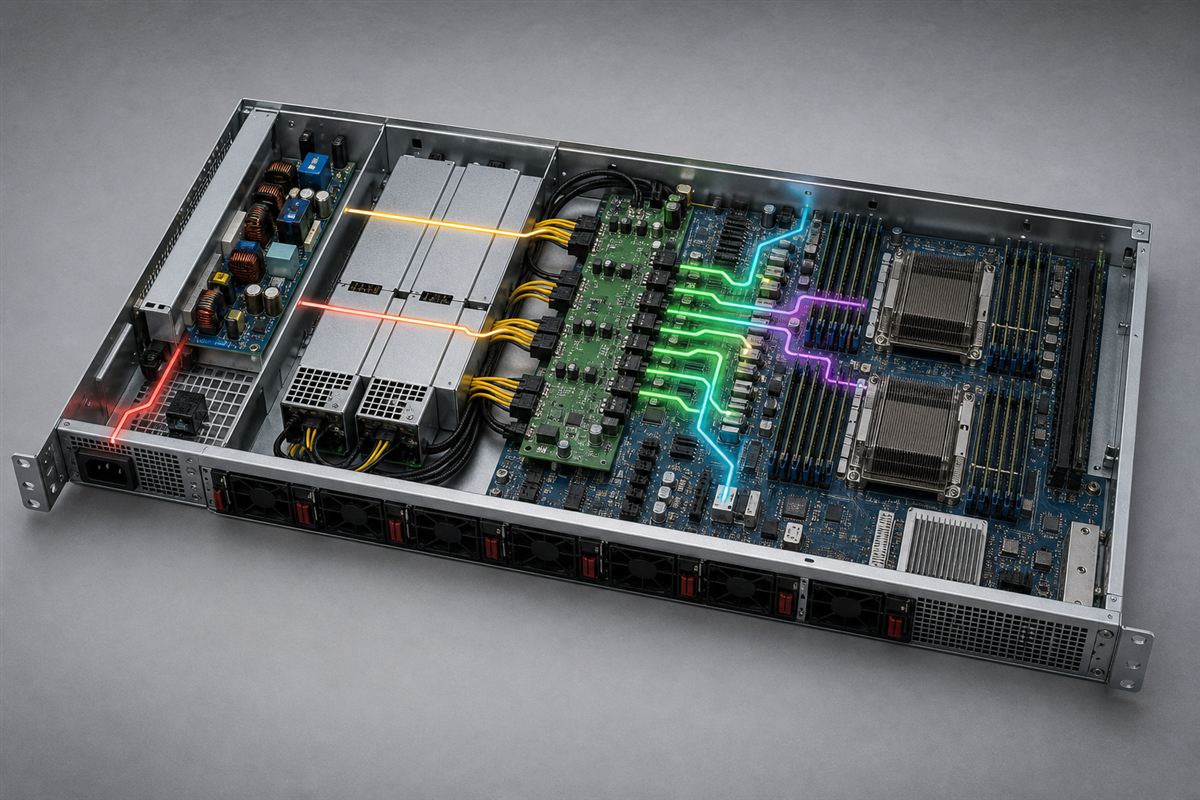
The PDB separates power conversion from power delivery
The PSU can produce a compliant output while the server still fails to deliver acceptable voltage at a load. Between the module and silicon are mating contacts, ORing or isolation devices, copper planes, busbars, cables, branch protection, connectors, and point-of-load regulators. Resistance and inductance across that path create voltage drop, heating, and transient response that cannot be assigned to the switching module alone.
The server power supply distribution board is the physical and electrical handoff between removable modules and load branches in many redundant platforms. Its current rating, connector map, control wiring, and cooling determine whether the PSU’s output can reach each load safely. A board designed for one chassis is not automatically interchangeable with another even if both accept modules of similar wattage.
For high-current buses, a small resistance produces meaningful loss because conductor heating follows current squared times resistance. This is why connector condition, contact engagement, copper cross-section, and branch balance matter more as bus current rises. A higher-voltage distribution architecture can reduce current for the same power, but it also changes conversion stages, protection, connectors, and load-side regulators. It is an architecture choice, not a drop-in PSU substitution.
A workload transient tests every switching stage at once
Server demand is not stationary. CPU power states, accelerator kernels, storage activity, and fan response can change electrical load quickly. At the first instant of a rising load, nearby capacitance supplies part of the energy. Point-of-load converters react, the distribution bus changes, the PSU feedback loop increases transferred energy, and the input stage draws the corresponding power from the DC link and facility source. Each boundary contributes to the observed voltage excursion and recovery.
This event chain gives “transient response” a practical meaning. A large nameplate wattage can provide thermal capacity without guaranteeing that a particular load step remains inside the host’s voltage-time envelope. Conversely, a well-matched lower-rated module may handle the supported configuration because the PDB, capacitance, controls, and workload power management were designed together. Platform approval is stronger evidence than wattage comparison.
Oscilloscope measurements at the relevant bus and load points can distinguish a module response problem from excessive distribution impedance or point-of-load behavior. Measurement bandwidth, probe placement, ground technique, trigger condition, and workload repeatability affect the evidence. BMC telemetry is valuable for trends and operational events, but its sampling rate may not capture the shortest excursions. The two forms of observation answer different questions.
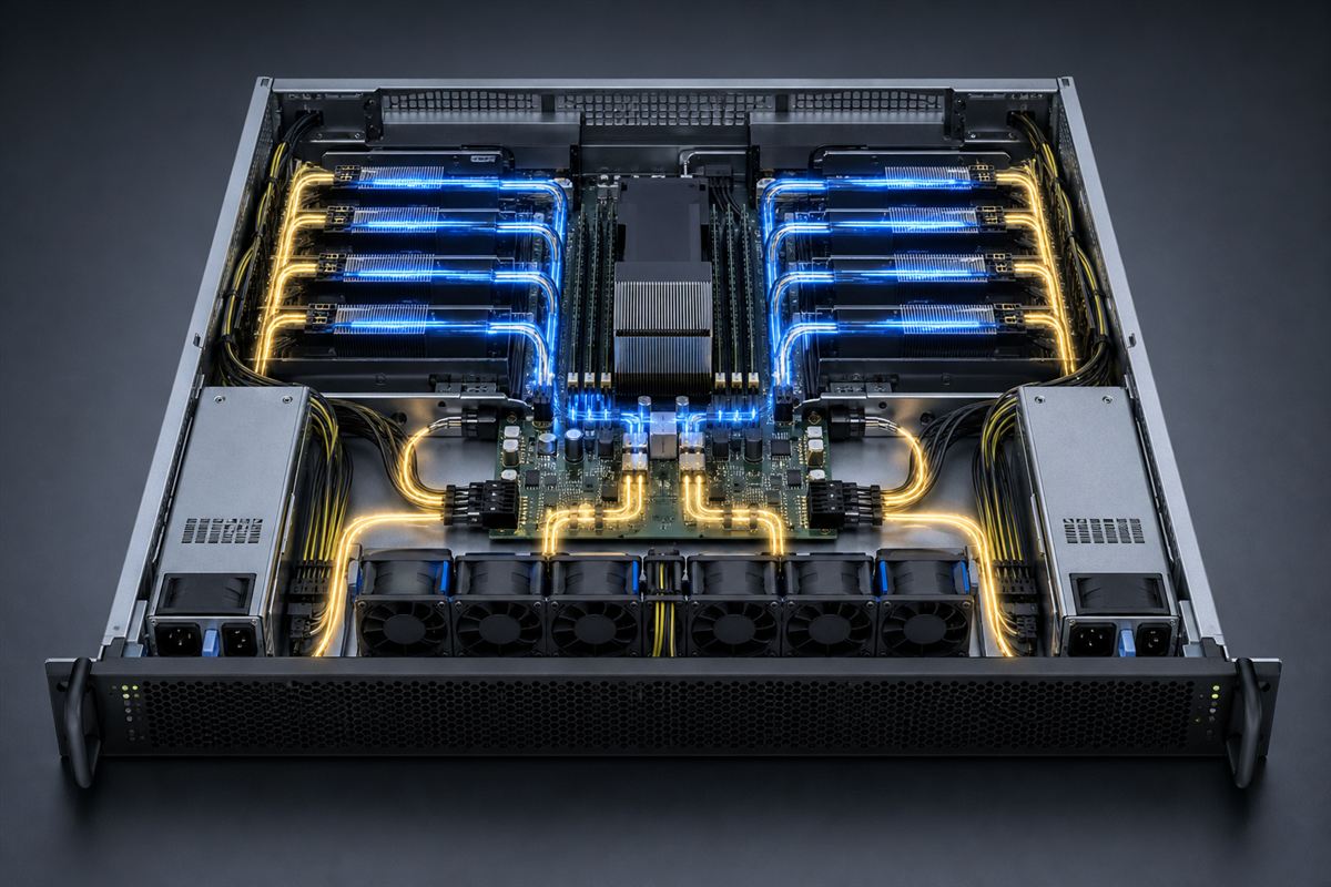
Redundant modules add controlled connection and disconnection
In a redundant server, two switching supplies can feed a common distribution bus through isolation and current-sharing mechanisms. The architecture must prevent a failed module from dragging down the shared output, manage insertion current, and transfer load without an unacceptable bus disturbance. Hot swap is therefore an electrical sequence as well as a mechanical feature.
Current sharing keeps paralleled units from carrying severely unequal portions of the load, but its exact method and tolerances are product-specific. During removal, the surviving module and distribution path must carry the supported server state. During insertion, connector sequencing, precharge or inrush control, output synchronization, and isolation behavior determine whether the new module joins the bus cleanly. These functions cannot be inferred from “switching power supply” alone.
Redundancy policy can also change the switching modules’ operating points. A platform may share load across both supplies or concentrate it on one under some conditions. That changes conversion loss, temperature, fan operation, and the size of the load step when the operating state changes. The supported firmware policy and single-module capacity remain part of the server design.
Digital management observes the converter but does not replace compatibility
Managed server PSUs may expose input, output, temperature, fan, status, warning, and fault information, depending on the model and host implementation. The PMBus application-profile library includes an application profile specifically for AC/DC server power supplies. That source confirms that server power management has a defined protocol context, while the exact supported commands and interpretations still belong to the particular PSU and platform.
The current PMBus specification page describes PMBus as a power-management protocol built on SMBus and identifies the published specification revisions. In engineering terms, the bus gives the BMC a structured way to communicate with power-conversion devices. It does not standardize the mechanical housing, high-current connector, output rating, airflow, or server firmware policy.
This boundary prevents a common selection error. Two supplies can both advertise PMBus yet differ in command support, scaling, manufacturer extensions, alert behavior, addresses, and host recognition. A replacement should be selected from the server’s supported options, then its telemetry can be used for health monitoring and fault diagnosis. Protocol presence is not a universal interchangeability mark.
Switching noise is managed across the complete enclosure
Fast voltage and current transitions enable compact conversion but can excite parasitic capacitance and inductance. Designers manage the resulting conducted and radiated emissions through topology, switching transitions, component placement, shielding, filtering, grounding, and enclosure construction. Output ripple and high-frequency noise likewise depend on the converter, distribution path, measurement method, and load.
A laboratory reading has meaning only when the probe technique and bandwidth match the requirement. A long ground lead can display ringing that belongs mainly to the measurement loop, while probing far from the PSU can include PDB and load-generated noise. The specification boundary should name where and how a limit applies. For a server integrator, the final enclosure and cable arrangement are part of electromagnetic behavior even when the PSU itself has passed its applicable evaluations.
Cooling is equally coupled. Switching, conduction, magnetic, rectification, and fan losses become heat inside a compact module. Blocked inlet area, recirculated exhaust, high altitude, elevated temperature, or an unsupported airflow direction can reduce the usable operating envelope. Published derating and airflow requirements for the exact module take precedence over assumptions based on another supply with a similar shell.
The conversion path defines the compatibility boundary
The phrase server switching power supply correctly identifies the conversion technology, but it is too broad to specify a replacement. A complete identity includes the supported server, input category, conditional output, mechanical envelope, blind-mate interface, primary bus, standby and control behavior, airflow, management implementation, fault response, and redundancy rules.
Following the energy path makes the selection logic concrete. The front end must suit the facility source; the high-frequency converter must produce the host’s required regulated bus; the PDB must deliver that bus through protected branches; point-of-load stages must tolerate real workload transitions; and management must recognize the module’s states. A mismatch at any boundary can defeat an otherwise capable SMPS.
That is also the useful distinction from an industrial switching supply or a DC-input server article. Industrial coverage centers on the machine cabinet and its environmental disturbances; DC-input coverage centers on the source and voltage boundaries. Server switching power is about the conversion mechanism and the coordinated path from facility input to rapidly changing digital loads. Once that path is named, “switching” stops being a vague product label and becomes an understandable system architecture.