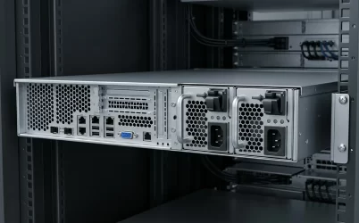
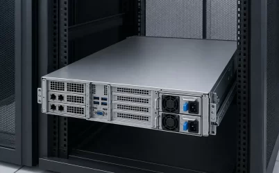
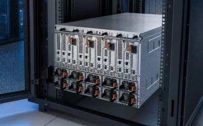
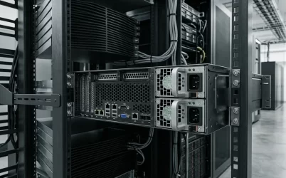
In the search results reviewed for this article, an unqualified “server PDB” query was dominated by Protein Data Bank resources. In server power hardware, however, PDB often means power distribution board: a board or assembly between one or more power-supply modules and the server’s downstream loads. The electrical meaning is narrower, context-dependent, and not a universal product definition. Before researching compatibility, pinouts, redundancy, or pricing, determine which acronym is intended and what physical object the document calls a PDB.
For server engineers and buyers, the practical objective is not to find one generic PDB specification. It is to identify the board’s boundary: what connects upstream, what receives power downstream, which functions reside on the board, and which functions remain in the PSU, motherboard, firmware, or external cabling.
Resolve PDB before opening a hardware drawing
The surrounding vocabulary usually distinguishes the two meanings. Protein records, molecular structures, sequence searches, APIs, and biological assemblies indicate the Protein Data Bank. The RCSB Protein Data Bank Data API, for example, provides programmatic access to structural biology data.
Power terms point elsewhere. References to CRPS modules, hot-swap bays, card-edge contacts, output harnesses, busbars, current sharing, motherboard power, or a redundant cage indicate a server power distribution board. Marketplace listings may be less disciplined, so the acronym alone should not authorize a purchase or an electrical assumption.
| Language near “PDB” | Likely meaning | Appropriate next step |
|---|---|---|
| Protein structure, molecule, sequence, API, accession code | Protein Data Bank | Use an official structural-biology database or API resource. |
| CRPS, PSU bay, blind-mate connector, 12 V or 48 V bus, motherboard harness | Server power distribution board | Identify the exact host, PSU family, board assembly, and revisions. |
| Rack outlets, metered receptacles, switched branches, rack input | Possibly a rack PDU, not a server PDB | Clarify whether the document means a power distribution unit. |
| “Server PDB” with no drawing, part number, or application | Undefined abbreviation | Request the full noun and the physical scope before interpreting it. |
Word order also changes intent. “PDB server” commonly describes an online service for biological data. “Server power distribution board” is much more likely to describe electrical hardware. Search refinements such as the host model, CRPS family, board number, output architecture, or chassis type help prevent the biology meaning from dominating the investigation.
Six different objects can inherit the same PDB label
Even after establishing the electrical meaning, “PDB” may not identify a consistent supply boundary. One seller may use it for a populated board; another may use it for a cage containing the board; a third may apply the term to a simple adapter. The object should be classified before its functions are discussed.
| Possible object | What it may contain | What the name does not establish |
|---|---|---|
| Bare PCB | Fabricated board with copper layers and drilled features but no functional component population | Completed distribution functions, connectors, protection, or usable electrical ratings |
| Populated power distribution board | Connectors, copper paths, components, sensing, control, or protection appropriate to one design | Compatibility with an unspecified PSU or server |
| Adapter or interposer | A short electrical and mechanical transition between two interfaces | Source combining, branch protection, management, or redundancy |
| Power backplane | One or more module receptacles and a board that transfers power and signals into the host | Whether a cage, harnesses, or PSU modules are included |
| Populated cage | Mechanical guides, retention features, module bays, and an installed board | Downstream cables, supported modules, or complete server integration |
| Complete power assembly | PSU modules, cage, PDB, harnesses, mounting hardware, and possibly management connections | Host approval or suitability unless the exact configuration is documented |
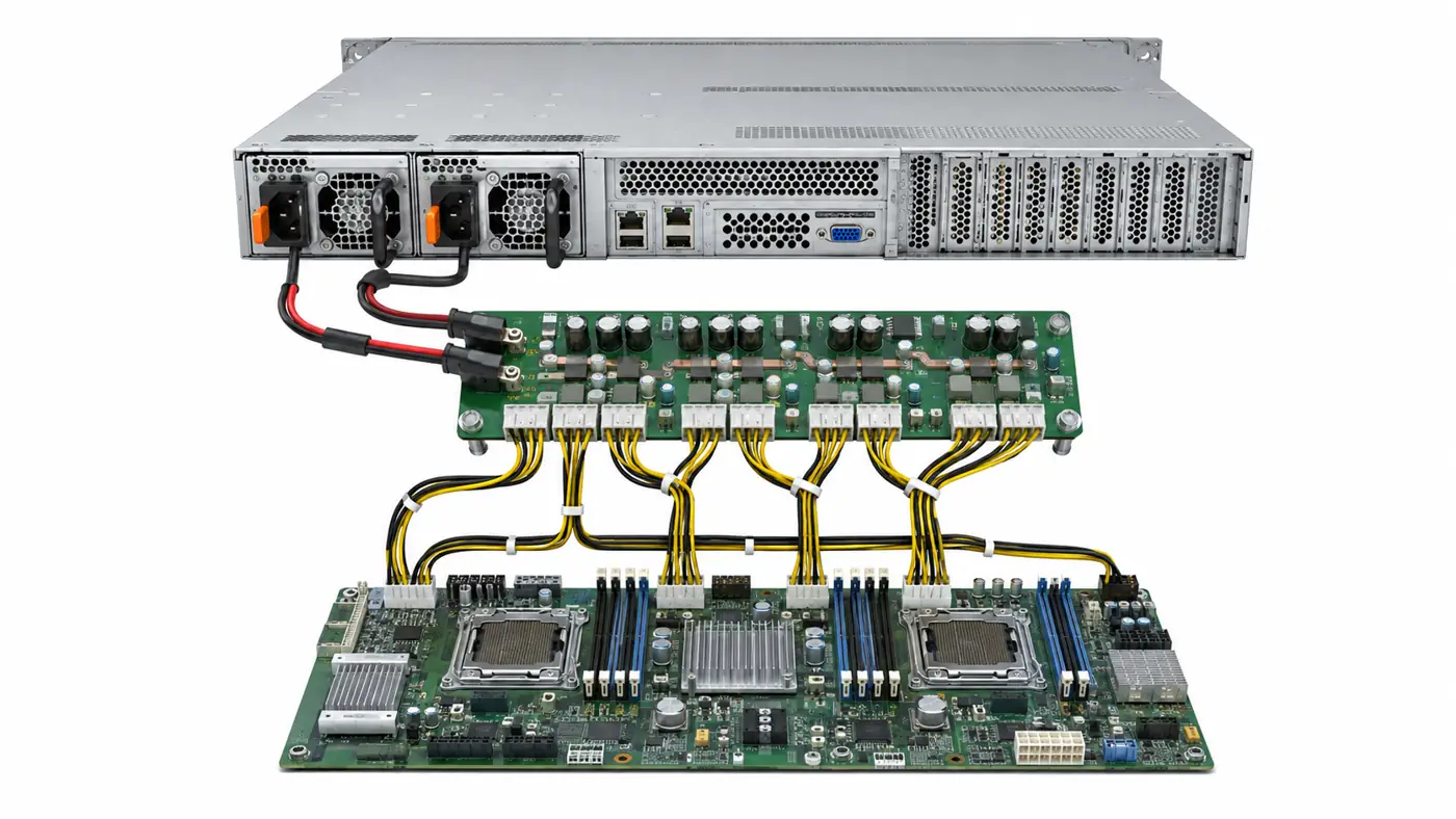
The distinctions are commercially and technically significant. A photograph of a metal cage may conceal whether the PDB is installed. A photograph of a populated board may not show the mating module, output harnesses, or mounting hardware. A listing for a “dual PSU PDB” may describe only the board, even though the displayed system includes two power modules.
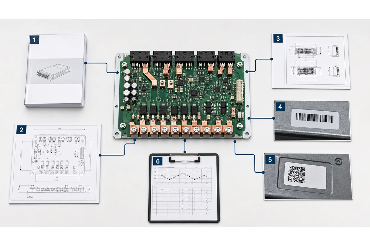
Physical inspection can help classify an unknown item, but appearance has limits. Similar card-edge receptacles can carry different assignments, and two boards with related layouts can have different revisions or host responsibilities. Useful identity evidence includes the board assembly number, revision, host platform, mating PSU designation, assembly drawing, and photographs showing both sides and all connector positions.
The server PDB boundary has four sides
A server PDB becomes understandable when it is drawn as a bounded component rather than treated as shorthand for the entire power system. Four sides of that boundary need names.
The upstream module relationship
The upstream side identifies what supplies the board. It may be one fixed power supply, one removable hot-plug module, a pair of CRPS-style modules, or another platform-specific source arrangement. The exact module and revision matter because the mechanical interface, high-current contacts, standby functions, control signals, and communications behavior can vary.
“CRPS compatible” narrows the ecosystem but does not by itself prove that an arbitrary CRPS module belongs in the assembly. The host documentation or an applicable interface definition must connect the module, board, and server configuration.
The downstream load destinations
The downstream side states where the PDB sends power. Depending on the platform, destinations may include a motherboard, processor power stages, accelerator branches, storage backplanes, fans, or auxiliary devices. Distribution may use board-mounted connectors, cables, copper bars, or direct board-to-board interfaces.
A voltage label does not complete this description. A board advertised as “12 V” may still differ in current capability, branch arrangement, connector assignment, auxiliary rails, sensing, protection, and return paths. A 48 V architecture likewise requires downstream conversion designed for that bus; it is not interchangeable with a 12 V host because both are server power systems.
The control and management boundary
Server power assemblies can exchange presence, enable, power-good, current-share, fault, identification, and management information. Some of those functions may pass through the PDB. Others may be generated, translated, isolated, or monitored on the board. Still others may connect directly between a PSU and the host controller.
Terms such as PMBus or SMBus should be tied to an exact implementation. The existence of a communication-capable contact does not establish address behavior, supported commands, telemetry accuracy, firmware interoperability, or how multiple modules share the bus.
The mechanical and thermal boundary
The board also occupies a physical relationship with the cage and chassis. Connector alignment, seating depth, retention, board supports, copper clearance, airflow obstruction, extraction space, and service access influence whether the assembly can be installed reliably. The PDB itself may be cooled by chassis airflow rather than a dedicated fan, so its thermal conditions depend on the surrounding server layout.
This four-sided view prevents the PDB from absorbing responsibilities that belong elsewhere. Point-of-load regulation may reside on the motherboard. Input conversion and some protection may remain inside the PSU. A cable assembly may define the final connector arrangement. Host firmware may decide how alarms are interpreted. The PDB’s role should be assigned from evidence rather than inferred from its central physical position.
Board functions must be assigned, not assumed
Several functions are commonly associated with server power distribution boards, but their placement varies by architecture. A useful document states which assembly performs each function.
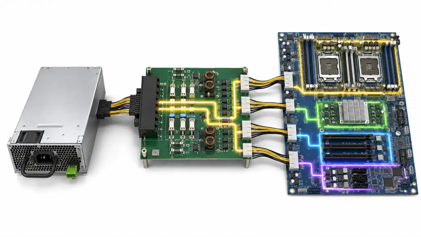
- Main-power conduction: The board may carry a high-current DC bus from the PSU interface to one or more output branches. Its usable capability depends on the complete current path, including contacts, copper, fasteners, cables, airflow, and applicable operating conditions.
- Source combining and isolation: In a multi-module system, source paths may be combined through circuitry located in the PSU, on the PDB, or across both. Two input receptacles do not independently prove redundant operation or fault isolation.
- Branch distribution and protection: A board may divide the main bus among motherboard, storage, fan, or accelerator destinations. Branch protection, sensing, and connector limits must be documented for the exact assembly.
- Standby or auxiliary power: Standby power may pass through the board, be converted on it, or be handled elsewhere. This path can remain active when the main output is off, making its ownership relevant to startup and service behavior.
- Status and management routing: The PDB may route or condition presence, health, sharing, and telemetry signals. Physical continuity does not prove that the host firmware supports every connected module.
A responsibility matrix can expose uncertainty without inventing details. Put each required function in a row and assign it to the PSU, PDB, motherboard, cable assembly, chassis controller, or “unresolved.” This is more reliable than assuming that every visible component on the board defines a complete feature. A fuse indicates some form of protection but does not reveal the protected branch, rating conditions, coordination, or service consequence. A controller IC does not by itself prove a specific management protocol or redundancy behavior.
Marketing descriptions require the same restraint. “Dual PSU board” establishes the presence of two source positions, not what happens when one disappears. “Hot-swap backplane” does not establish that live removal is permitted under every workload. “Universal server PDB” should be treated as an unproven claim until the supported module, host, electrical interface, and mechanical assembly are named.
Send each unknown to the document that can answer it
Once the object and boundary are clear, the remaining question usually belongs to a more specialized investigation. Keeping those territories separate prevents a broad server PDB definition from turning into an unsafe universal pinout or an incomplete redundancy claim.
- For redundancy and failed-source behavior: Establish the supported module population, combining method, isolation, surviving capacity, shared elements, and required host behavior. Powernexu’s analysis of the 1+1 CRPS power distribution board examines that failure-boundary problem in detail.
- For purchase scope: Determine whether the quoted item is a bare board, populated PDB, cage, harness set, or complete subsystem. The separate CRPS redundant power backplane specification addresses how that assembly boundary should remain stable through quotation and acceptance.
- For connector mapping: Name both mating assemblies at every interface, then obtain the relevant connector drawing, cable schedule, or host documentation. Connector family and physical mating are not sufficient evidence of electrical equivalence.
- For contact-level work: Use an exact PSU, PDB, host, connector orientation, and revision-controlled source. Unknown contacts should remain unknown rather than being copied from a visually similar module.
- For mechanical integration: Obtain the board and cage drawings, connector datum, mounting points, PSU insertion path, output-cable clearance, and airflow constraints. A board that appears to fit can still misalign at the blind-mate interface.
- For host support: Use the platform manufacturer’s service documentation, approved parts records, or explicit supplier evidence. An electrically plausible combination is not automatically an officially supported server configuration.
Different documents have different authority. A seller photograph can establish visible construction but not hidden routing. A PCB fabrication file describes geometry but may not define the completed assembly. A PSU datasheet describes the module but cannot, by itself, establish the host’s PDB outputs. A host manual may identify approved spares without disclosing every contact. The claim should never extend beyond what its source can support.
Write an identity statement that survives handoff
Record the result in one controlled statement:
In the identified server and chassis revision, “PDB” means the specified board or assembly. It mates upstream with the named PSU module and revision, supplies the listed downstream destinations, performs only the documented board-resident functions, and is governed by the referenced assembly, interface, and host documents.
List unresolved items separately. A drawing may prove dimensions and connector positions while leaving current limits, management behavior, or approved substitutions unknown. Such evidence can support identification without authorizing energization or interchangeability.
This definition gives engineering, purchasing, service, and suppliers the same object and scope. It also keeps a Protein Data Bank service, rack PDU, bare adapter, and complete CRPS assembly from being conflated.
“Server PDB” becomes actionable only after its meaning and physical boundary are explicit. Redundancy, connectors, pinouts, mechanical fit, and purchase scope can then be evaluated through the specialized evidence appropriate to each question.