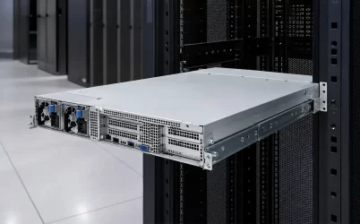
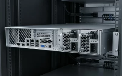
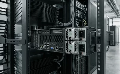
A blade server power supply should be qualified against the complete chassis configuration, not selected from module wattage or physical resemblance. Before purchasing a replacement or new power assembly, identify the exact chassis and revision, PSU bay population, installed blade configurations, shared power-distribution hardware, management policy, input conditions, cooling direction, and workload that must remain online after a permitted failure. The acceptable candidate is the module or assembly that the platform documentation supports in those conditions. A higher-rated module is not automatically compatible, and a physically matching module does not prove that the chassis can recognize, cool, share load with, or safely operate it.
Quick answer: qualify the chassis population, not an isolated module
A blade PSU powers a shared enclosure containing compute blades and, depending on the platform, fans, management controllers, interconnect modules, and other common loads. Build the purchase around a named chassis population and its required degraded state. Record the exact PSU identity, supported quantity, input condition, airflow, pairing rules, and power mode. Then establish whether the documented surviving PSU configuration can carry the permitted blade population and workload. If the available evidence covers only the module rating but not the chassis configuration, the replacement remains unqualified.
Power is shared across a blade enclosure
A rack server commonly has a direct relationship between one motherboard and its PSU assembly. A blade platform moves that boundary outward. Removable power modules feed a chassis-level midplane, power backplane, or equivalent distribution assembly, which then supplies multiple blade slots and shared components. The exact topology varies by manufacturer and generation, so “blade server power supply” does not identify one universal connector, output bus, redundancy mode, or mechanical format.
The practical unit of analysis is the powered enclosure. Its relevant layers include:
| Chassis layer | Question that affects the PSU decision | Consequence of an unresolved answer |
|---|---|---|
| Compute population | Which blade models, processor configurations, memory, storage, and adapters occupy each slot? | The chassis load and permitted degraded population cannot be established. |
| Shared distribution | Which midplane, power backplane, connectors, and bus structures carry power from the PSU bays? | Mechanical insertion may succeed even though the electrical assembly is unsupported. |
| PSU population | Which exact modules and revisions are installed, and what combinations does the chassis support? | A replacement may fail pairing, recognition, load sharing, or power-policy requirements. |
| Management | How does the chassis report capacity, health, redundancy, and power caps? | An electrically active module may still leave the enclosure in a degraded or unsupported state. |
| Cooling | What airflow direction, fan population, inlet condition, and blanking arrangement apply? | The supported blade or PSU population may be lower than the nameplate rating suggests. |
| Rack source | Which input voltage, cords, outlets, PDU branches, and upstream feeds supply the PSU bays? | The modules may energize but fail to deliver the required documented output or feed resilience. |
This relationship also explains why a broad server PSU form-factor category can narrow the search without proving interchangeability. The blade chassis still controls rail alignment, insertion depth, latching, blind-mate position, electrical contacts, control behavior, airflow, and removal clearance.
A slot map becomes the blade chassis load model
Begin with a slot-by-slot record rather than an estimated average load per blade. Two blades that occupy the same mechanical slot can present different power requirements because of their processors, memory population, local storage, accelerators, mezzanine cards, firmware policy, and workload. Chassis fans and interconnect modules can also change demand independently of compute-slot occupancy.
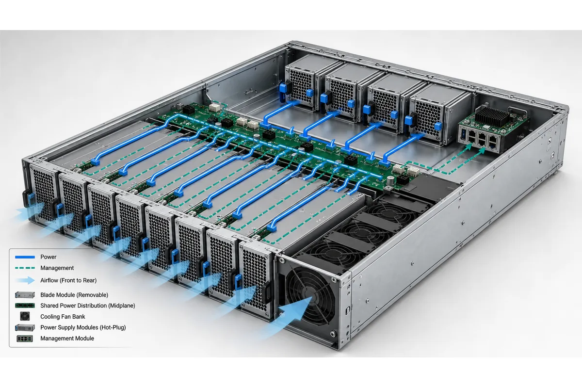
The population record should name the exact blade configuration in every occupied slot and identify reserved or temporarily empty positions. If the platform requires fillers, airflow baffles, or a particular fan population for unused slots, preserve those conditions as part of the configuration. Do not infer them from another chassis family.
For each planned population, distinguish at least three quantities:
- Observed demand is the load seen during a measured workload at a stated boundary and time. It may not represent startup, peak activity, or a permitted future configuration.
- Budgeted demand is the capacity assigned by the chassis management policy or vendor planning method. It may include reservations or power caps that differ from measured consumption.
- Supported maximum is the limit documented for the exact chassis, module population, input condition, and cooling state. It should not be reconstructed from unrelated component ratings.
Processor or accelerator thermal design power is not a complete chassis power figure. It omits conversion losses, memory, storage, fabric modules, fans, management, and differences between workload states. Where the manufacturer provides a chassis power calculator or configuration tool, use the version applicable to the installed platform and retain its inputs with the result.
Capacity must survive the required chassis states
The relevant capacity is the lowest documented power available across every operating state the service plan requires. In plain terms, required chassis demand must remain within the supported available capacity not only with all PSUs healthy, but also after the specific module or feed event the redundancy policy claims to tolerate.
Available capacity in a state may be constrained by more than the sum of active module labels. The chassis distribution limit, input voltage, inlet temperature, airflow, firmware policy, module pairing rules, and permitted aggregation mode can all establish a lower boundary. In a 1+1 configuration, for example, protected capacity is generally bounded by the supported output of one surviving path. In a capacity-plus-redundancy arrangement with more modules, the result depends on how many modules the load requires and which failures the platform supports.
| Chassis state | Question to resolve | Evidence needed |
|---|---|---|
| Normal operation | Can the installed PSU population support the configured blades and common loads? | Platform power inventory, applicable module ratings, and management status |
| Workload peak | Does the required workload remain inside the chassis policy without unplanned power capping? | Representative workload data and the documented power-management behavior |
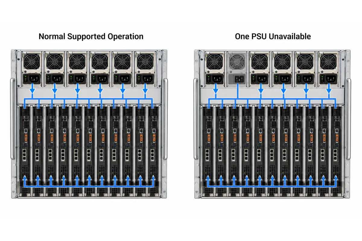
| One PSU unavailable | Which blade population and workload can the remaining supported configuration carry? | Manufacturer-defined redundancy mode and surviving-capacity data |
| One rack feed unavailable | Which PSU bays remain energized, and is their combined supported capacity sufficient? | Bay-to-feed map, rack PDU records, and chassis power policy |
| Service restoration | Does insertion of the replacement restore the intended module population and protected state? | Host recognition, alarms, inventory, and redundancy status |
Keep module wattage separate from protected chassis capacity. Powernexu’s discussion of redundant server power supply ratings explains how module output, efficiency, derating, and one-surviving-module capacity answer different questions. In a blade chassis, those distinctions must then be reconciled with the platform’s supported blade population.
If the enclosure can continue running only by applying power caps, disabling selected blades, or restricting workload, document that as the permitted degraded state. It may be operationally valid, but it is not equivalent to sustaining the unrestricted normal population.
The shared distribution path decides where redundancy stops
Multiple PSU modules reduce exposure to an individual converter failure only within the topology the chassis implements. They may still share a power backplane, bus structure, management controller, cooling system, or downstream connector. A failure in one of those common elements can affect several PSU bays or every blade even when all removable modules remain healthy.
Create a chassis power-path drawing that starts at each PSU inlet and ends at the blade slots and common loads. It should identify which elements are duplicated, which remain shared, and where electrical isolation occurs. Manufacturer documentation may describe current sharing, fault isolation, or supported power modes, but those functions should not be assumed from the presence of several PSU handles.
The map should distinguish four events that can look similar in an alert log:
- A module fault removes one converter while its bay and upstream source remain available.
- A bay or mating-interface fault can prevent a known-good module from operating in one position.
- A feed event can remove several correctly functioning modules assigned to the same rack source.
- A shared distribution or cooling event can affect the complete enclosure rather than one PSU path.
This distinction changes both spare strategy and incident response. Repeatedly replacing modules will not correct a damaged bay, shared power-distribution fault, incompatible revision, or upstream feed problem.
Rack feeds and cooling can change the supported population
Map each PSU inlet to its rack PDU outlet and upstream source according to the chassis manufacturer’s supported allocation. Alternating cord positions or using two differently colored PDUs does not by itself prove that the required blade population survives a source loss. The surviving PSU bays must remain energized, and their documented capacity must fit within the PDU branch, cord, outlet, and facility limits.
AC infrastructure planning also uses a different measurement boundary from chassis DC capacity. Rack PDU current is based on PSU input under the relevant operating condition, while a module’s output rating describes delivered DC power. Conversion efficiency, input voltage, sharing policy, and degraded operation influence the relationship between them.
Cooling belongs in the same population model. Blade enclosures concentrate compute, switching, conversion, and fans in a compact volume. If one PSU becomes unavailable, the remaining modules may operate at a higher load and dissipate more heat. If a fan or airflow condition is also degraded, the chassis may reduce the supported power envelope or change fan behavior. Use the limits and airflow direction documented for the exact platform.
The platform-specific nature of these conditions is illustrated by the Cisco UCS 5108 technical specifications, which publish power-input and environmental information for that named chassis. Those values are evidence for the UCS 5108 configuration described by Cisco; they are not universal blade-server limits.
One search phrase can describe four purchase scopes
A commercial listing for a blade server power supply may refer to one removable module, a supported module population, a chassis power kit, or an enclosure containing the complete power subsystem. Price comparisons are meaningful only after the supplied object is explicit.
| Purchase scope | Appropriate situation | Information the quotation must preserve |
|---|---|---|
| Single replacement module | An existing qualified chassis needs an exact spare or documented supersession. | Manufacturer, ordering and part numbers, revision, condition, supported chassis, and pairing restrictions |
| Supported module population | The platform requires a defined quantity or matched configuration for the intended power mode. | Module quantity, identities, revisions, supported operating mode, and exclusions |
| Chassis power kit | A new integration or repair requires modules plus cages, distribution hardware, cords, or mounting parts. | Complete bill of material, assembly revision, harnesses, mechanical parts, and documentation |
| Complete blade enclosure | The purchaser needs a chassis-level platform rather than a PSU component. | Chassis identity, installed power and cooling populations, management hardware, included accessories, and supported blade configurations |
For a replacement, start with the chassis service record and labels on the installed modules. Reconcile the manufacturer’s marketing number, ordering number, regulatory or internal part number, and revision because different identifiers may refer to the same unit—or superficially similar identifiers may separate incompatible variants. A seller’s cross-reference should be treated as a claim requiring platform evidence, not as proof by itself.
The request for quotation should also state the deployed input, airflow direction, intended PSU quantity, blade population, redundancy mode, and required degraded workload. Ask the supplier to identify included cords, handles, cages, distribution boards, harnesses, and mounting hardware rather than assuming that a photograph represents the delivered scope. If substitutions are permitted, require the substitute’s exact identity and supporting chassis documentation before shipment.
At receiving, verify part number, revision, quantity, keying, airflow orientation, connectors, condition, and included hardware. Install only under the platform procedure, then confirm chassis recognition, expected PSU population, alarms, fan behavior, power budget, and intended redundancy state. Output alone is not acceptance if management reports an unsupported or degraded configuration.
Perform a module-removal or feed-loss check only when manufacturer documentation, workload margin, site safety, and continuity procedures permit it. After restoration, confirm the complete supported state. Record the PSU identity against the chassis revision, blade population, power mode, input, cooling, and management baseline so future reorders preserve the qualified configuration.