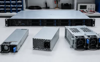
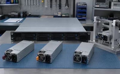
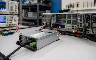
A 250W 80 PLUS 1U server power supply is a viable candidate only when its documented output can support the server’s highest credible DC load state under the intended input, temperature, and airflow conditions. The 250W label does not establish rail-level capacity, while “1U” describes the host’s rack height rather than a universal PSU envelope. An 80 PLUS claim addresses conversion efficiency under defined test conditions; it does not prove load adequacy, host compatibility, or reliability. Build the load budget first. If the candidate passes, continue to the exact mechanical drawing, connectors, cooling direction, input range, and model-specific efficiency evidence.
The go/no-go rule for a 250W candidate
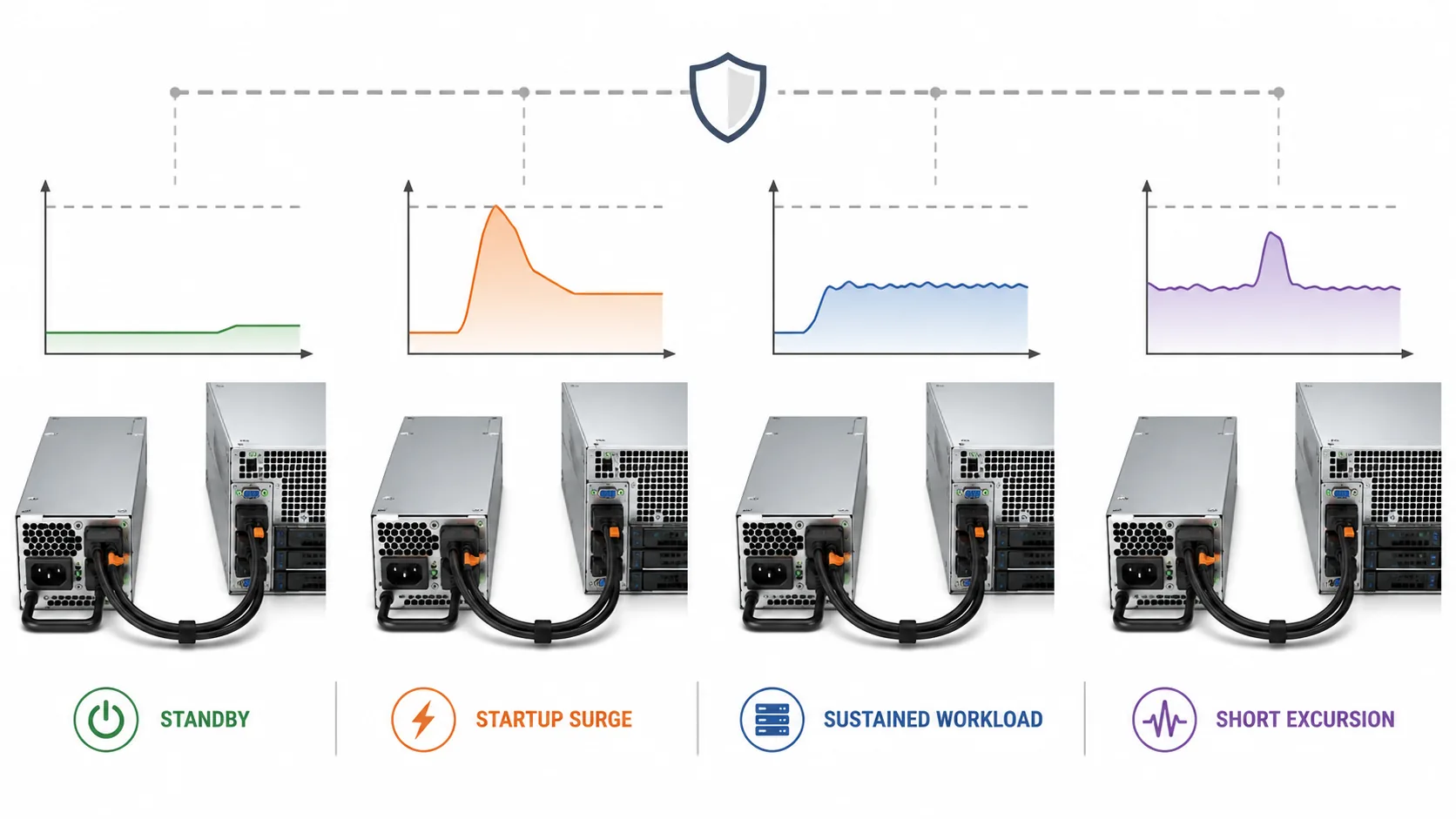
The required DC output is the highest credible demand among power-on, sustained workload, bounded workload excursions, and the planned configuration. That result must remain within the exact PSU’s total and rail-specific limits under the applicable rating conditions. A candidate that passes only an average wall-power measurement has not passed this test. A candidate that passes the output calculation can still be rejected by an unsupported host, a conflicting connector map, insufficient cable reach, an incompatible airflow direction, or a mechanical envelope that obstructs installation and service.
This order matters. Measuring a chassis to accommodate a 250W supply is wasted work if the workload can demand more power than the supply is documented to deliver. Conversely, a comfortable load result does not convert a Flex ATX or similarly packaged product into a universal 1U replacement.
First identify whether this is replacement or new integration
The same product search can support two materially different jobs. An exact replacement seeks to restore a known server configuration. New integration asks whether a compact PSU can become part of a server or appliance that has not already been qualified with it. The evidence and engineering responsibility are different.
| Purchase path | Controlling evidence | What the 250W calculation authorizes | What remains unresolved |
|---|---|---|---|
| Exact supported replacement | Host service documentation, installed PSU identity, and documented supersession | Confirms that the existing configuration has not outgrown its supported power option | Condition, revision, permitted substitutions, and restoration procedure |
| Platform-supported option or upgrade | Server manufacturer’s option matrix and configuration rules | Tests whether the planned CPU, memory, storage, and add-in population fit the supported option | Firmware, cable kit, bracket, thermal policy, and other platform dependencies |
| New compact-server integration | Exact PSU documentation plus system-level mechanical, electrical, and thermal design | Establishes whether 250W is a credible output class for the intended states | Mounting, connectors, protection, cooling, EMC, safety, and final-system responsibility |
For a supported replacement, the host’s approved part relationship normally has more authority than a marketplace description. A visually similar 250W unit is not an equivalent spare unless the platform documentation says so. For new integration, there may be no host authority to close the gaps; the system designer must therefore resolve every interface and preserve the operating conditions behind the PSU rating.
Build the 250W budget from operating states
Measure or estimate power at a clearly named boundary. The relevant comparison is normally the DC output demanded from the PSU, not the AC power measured at the wall. Wall input includes conversion loss, so comparing it directly with a 250W DC output rating mixes two different quantities.
Organize the server into load branches such as the motherboard and processor, memory, storage, fans, PCIe devices, management electronics, and any external device powered from the same supply. Then determine which branches can demand power simultaneously in each state.
| Load state | Demand that can dominate | Useful evidence | Common budgeting error |
|---|---|---|---|
| Power-on and startup | Fan acceleration, storage spin-up, charging, board initialization, and processor activity occurring together | Instrumented startup capture or bounded component and platform data | Using the lower idle value observed after boot |
| Sustained workload | Long-duration processor, storage, network, and fan demand at the intended operating point | Representative workload measurements with configuration and ambient conditions recorded | Using a short average that omits thermal fan response |
| Workload excursion | A short coincident increase that may be missed by slow telemetry | Measurement with bandwidth and sampling appropriate to the event | Assuming a monitoring average captures every relevant peak |
| Planned configuration | Added drives, memory, an expansion card, faster fans, or another authorized load change | Configured branch estimate using documented limits or measurements | Adding a percentage without identifying what will actually change |
The total-power screening value can be expressed as:
Required output = maximum of the startup, sustained, excursion, and planned-configuration requirements.
Each state should already include the loads that can occur together and a defensible allowance for measurement uncertainty, unit variation, or a specifically planned addition. Do not add several overlapping margins blindly. For example, if the planned-configuration state already includes two future drives at their startup demand, adding a second generic “future storage” percentage would count the same change twice.
A hypothetical 250W screening example
Consider a compact server for which measurements and component records produce the following illustrative DC-output requirements. These figures are hypothetical and do not describe a particular PSU or server.
| State | Calculated or measured DC requirement | Result against a nominal 250W ceiling |
|---|---|---|
| Power-on and startup | 176W | Below the ceiling |
| Sustained application workload | 162W | Below the ceiling |
| Bounded workload excursion | 218W | Below the ceiling |
| Planned configuration at its governing state | 232W | Below the ceiling by 18W |
The arithmetic leaves 18W, or 7.2% of the nominal rating, between the largest modeled state and 250W. That is not automatically an acceptable engineering margin. The candidate remains on hold until the exact model’s rating conditions, rail limits, connector limits, transient behavior, and required uncertainty are considered. A documented temperature derating or a constrained output rail could eliminate the apparent reserve.
Total watts are only the first inequality. If most of the server demand is concentrated on one output rail, that rail’s documented current or combined-power limit may govern before total output reaches 250W. A cable or connector can impose another lower boundary. The worksheet should therefore include total output, each loaded rail, every relevant connector branch, and the return path rather than treating the nameplate wattage as a single unrestricted pool.
Apply the rating conditions without subtracting efficiency twice
A PSU output rating belongs to stated operating conditions. Review the exact model’s accepted input range, frequency where applicable, inlet temperature, airflow assumption, orientation, altitude restrictions if documented, and any derating rule. A 250W headline may apply throughout the documented range, or it may depend on conditions that the compact chassis does not provide. Only model-specific documentation can answer that question.
Efficiency belongs on the input side of the calculation. If the server needs a DC output of PDC and the PSU efficiency at that operating point is η, approximate AC input is:
PAC = PDC / η
Use an efficiency value only when it applies to the exact model, input condition, and relevant load point. Do not reduce a documented 250W DC output rating by the conversion loss; the loss is reflected in the higher AC input. Likewise, do not assume that an 80 PLUS label increases the available DC output.
After capacity passes, prove the exact 1U fit
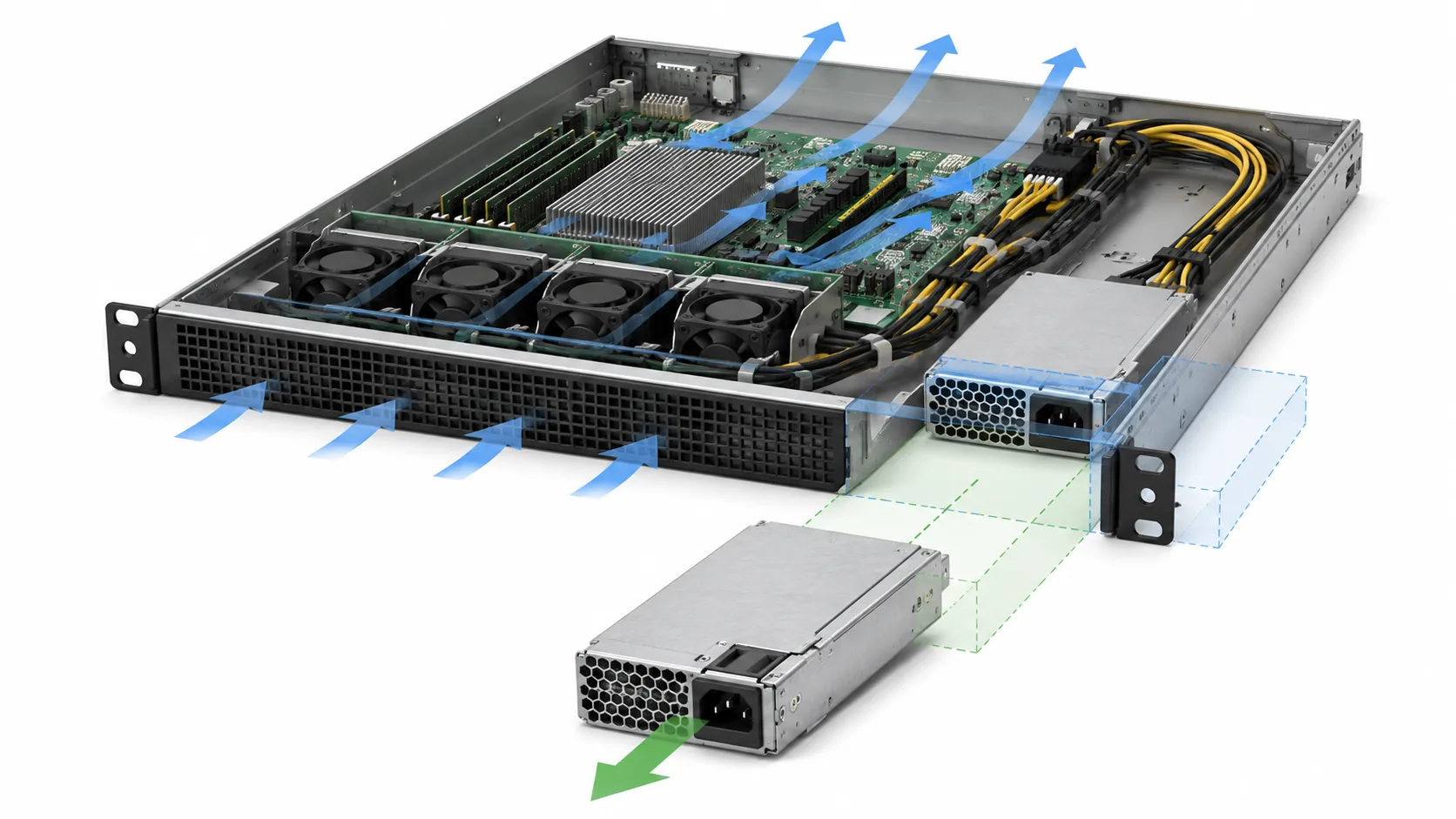
“1U” identifies host height, not a universal PSU envelope. Compare the exact PSU drawing with the chassis from common datums. Record body protrusions, mounting points, inlet and harness positions, cable bend and reach, ventilation keep-outs, nearby obstructions, and the complete installation/removal path. A server PSU mechanical fit drawing should preserve these checks instead of reducing fit to three dimensions.
Verify the documented cooling method and airflow direction in the installed orientation. Keep inlet and exhaust paths clear and prevent recirculation. If the host cannot maintain the model’s documented cooling conditions, do not assume full 250W output.
The electrical interface can reject a physically fitting PSU
Two compact power supplies can share similar housings while providing different connectors, pin assignments, rail distributions, cable lengths, standby functions, or control behavior. For an exact replacement, use the supported part identity and host documentation. For new integration, map the path from the AC inlet through the PSU to every motherboard, storage, fan, and accessory load.
The server PSU connector interface map should identify both sides of every connection and distinguish mechanical mating from electrical compatibility. At minimum, establish:
- the input connector, cord, grounding arrangement, and intended source;
- each output connector and its exact destination;
- rail voltage, polarity, current path, and applicable connector limit;
- standby, power-enable, power-good, fan, or other control functions where present;
- cable length, wire routing, strain relief, and service access; and
- whether any adapter changes pinout, protection, resistance, or responsibility.
Do not infer a pinout from connector appearance. An adapter can make two shells mate while leaving an electrical or control mismatch unresolved. It can also add resistance or create an unprotected branch that was absent from the original design.
Use 80 PLUS as efficiency evidence, not a system certificate
An 80 PLUS claim should be traceable to the exact manufacturer and model being offered. Record the applicable efficiency class, model identity, and test or listing conditions rather than relying on a reseller title, badge image, or specification copied from a neighboring product.
Model-specific documentation remains necessary even when the efficiency claim is valid. Seasonic’s SSP-250SUB datasheet, for example, is the type of primary model record used to investigate electrical ratings, mechanical information, connectors, and applicable operating conditions. Its contents apply to the identified product and should not be transferred to another 250W candidate merely because both search results mention 1U, Flex ATX, or 80 PLUS.
Keep the claims separate:
- 250W concerns documented output capacity under stated conditions.
- 80 PLUS concerns conversion-efficiency evidence at defined test points and conditions.
- 1U concerns the host’s rack-height category, not universal PSU dimensions.
- Compatibility depends on the exact host, mechanics, connectors, electrical behavior, cooling, and support relationship.
A verified efficiency claim therefore cannot repair a failed load budget or an incompatible interface. It becomes useful after the candidate’s identity and deployment conditions are known, particularly when estimating AC input, heat from conversion loss, or operating cost near the expected load points.
A purchase-ready candidate closes eight gates
| Gate | Evidence needed | Hold or reject condition |
|---|---|---|
| Product identity | Exact manufacturer, model, revision, and supplied configuration | Seller may ship an unspecified equivalent |
| Load adequacy | Startup, sustained, excursion, and planned-configuration DC requirements | Any required state exceeds a supported limit or remains unbounded |
| Rating conditions | Applicable input, temperature, airflow, orientation, and derating documentation | The host cannot preserve the conditions behind 250W output |
| Rail and branch limits | Exact rail, combined-power, connector, and cable limits | Total watts pass but one path is overloaded or undocumented |
| Mechanical fit | Controlled drawing compared with the chassis, including installation and service space | Envelope, mounting, cable bend, or extraction path conflicts |
| Electrical interface | Connector definitions, pin assignments, control functions, and load destinations | Compatibility depends on appearance or an undocumented adapter |
| Cooling | Airflow direction, ventilation clearances, and supported thermal condition | Chassis airflow contradicts or cannot satisfy the PSU requirement |
| Efficiency claim | Evidence tied to the exact model and applicable conditions | The claim exists only in a marketplace title or belongs to another model |
The order line should preserve the exact model and revision, quantity, included cables or brackets, applicable documentation, target host or assembly, and permitted substitutions. For an approved replacement, it should reference the supported server configuration. For new integration, it should identify unresolved system responsibilities rather than disguising them as supplier assumptions.
If the 250W budget fails, changing brackets or selecting a more efficient model does not solve the capacity problem; reduce the authorized load or move to an appropriately rated power architecture. If the budget passes but fit, interfaces, or cooling remain unresolved, keep the candidate in an engineering-review state rather than treating it as orderable. A 250W 80 PLUS 1U server power supply becomes a defensible purchase only when the load states fit inside its documented output envelope and the exact hardware can be installed, connected, cooled, and supported in the intended server.