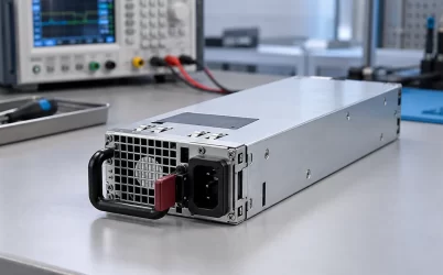
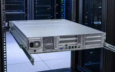
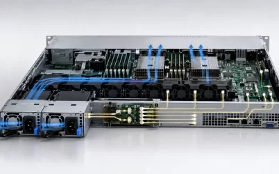
A CRPS 1+1 redundant power supply backplane is the hardware boundary that decides whether two removable power modules form a resilient power path or merely occupy two bays. In a true 1+1 arrangement, either supported module must be able to carry the required server load after the other module, its input feed, or its connection is removed from service. The backplane must combine the outputs without allowing one failed source to collapse the shared bus, and every downstream conductor must tolerate the resulting single-module current.
The practical question is therefore not simply whether a board has two CRPS connectors. Engineers need to establish the module-to-backplane interface, isolation method, current-sharing behavior, surviving-path rating, standby and management functions, downstream distribution, and the faults that the architecture is intended to survive. These properties belong to a defined assembly and cannot be inferred from a similar connector or the words “CRPS compatible.”
The backplane defines the redundancy boundary
Two power supplies do not automatically create two independent power paths. A server may have separate modules and separate power cords while still sharing a cage, backplane connector, current-combining stage, fuse, busbar, output harness, or motherboard inlet. Each shared element is part of the common failure boundary. The system can remain tolerant of one module failure while still being vulnerable to a backplane short, an undersized connector, or a single upstream circuit feeding both inputs.
A useful architecture drawing begins at the AC source and ends at the host load. It identifies the two input feeds, both CRPS modules, their mating contacts, output isolation devices, current-sense elements, shared copper, branch protection, standby path, management connection, and every downstream connector. This drawing separates module redundancy from feed redundancy and distribution redundancy. If both modules connect to the same PDU branch, loss of that branch defeats the input side even when the modules themselves are healthy.
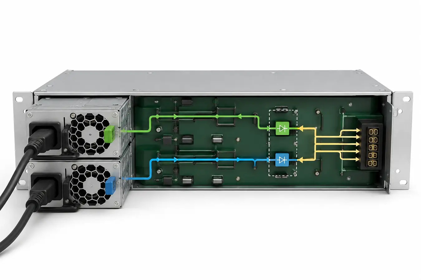
Output isolation must contain a failed source
Parallel outputs require a controlled way to prevent reverse energy from flowing into an unpowered or faulted module. Depending on the documented design, this function may use ideal-diode controllers, MOSFET-based ORing, other active isolation, or an equivalent method implemented within the module, on the backplane, or across both. Its physical location matters because it determines which faults can be isolated and which copper remains common.
The important evidence is not a generic topology name. The design record should show the fault direction that is blocked, the voltage drop and power dissipation of the isolation path, the expected behavior during insertion and removal, and the protection response if a source or downstream branch is shorted. A schematic excerpt without component ratings or thermal context cannot establish that the path is suitable for the intended current.
Hot insertion adds another transient condition. Connector contacts do not necessarily mate at the same instant, and input or output capacitance can create inrush current. The module, connector sequencing, backplane control and host behavior must be evaluated as one interface. “Hot-plug” should describe a supported operating procedure for the complete server configuration, not merely a removable handle on the PSU.
Current sharing protects normal operation, not surviving capacity
When both modules are healthy, a supported pair may share load so that neither module carries the entire demand. Sharing reduces individual thermal stress and can provide operating margin, but it does not change the capacity requirement for a protected 1+1 state. If the server must continue operating after one module is lost, the remaining module and the complete downstream path must support the required load under the documented input, temperature, airflow and altitude conditions.
Suppose a server has a sustained DC demand of 820 W and a short, documented operating excursion to 940 W. A proposed module may have a headline rating above that demand, but the comparison is incomplete until the available output under the actual rack input and inlet condition is known. The surviving path must also include the backplane isolation loss, connector heating and any branch limitation. This hypothetical example illustrates the method; it is not a rating for a particular Powernexu product.
Sharing accuracy also affects the healthy two-module state. A persistent imbalance can cause one module to approach a thermal or current limit sooner than expected. The host may need to recognize a degraded module, a communication mismatch or a current-share fault before output is lost. Telemetry is useful for detecting the condition, but management data does not replace electrical protection.
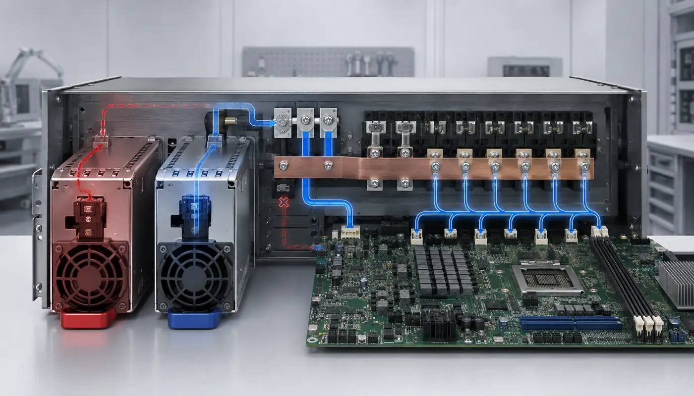
The PDB must carry the single-module current
Backplane capacity is distributed across several physical features. Card-edge contacts, press-fit pins, copper planes, busbars, vias, current-sense shunts, fuses, hot-swap devices and branch connectors can each become the limiting element. A board described only by total wattage conceals the voltage, current, temperature rise and airflow assumptions that make that wattage possible.
For low-voltage, high-current server buses, small resistance matters. Conduction loss follows the square of current, so a connector or copper path that appears acceptable during shared operation can run much hotter after one module assumes the full load. The surviving-state review should follow the complete current route from the active module contact through the PDB and into every relevant load branch. Local temperature rise and voltage drop should be evaluated at the actual current distribution, not estimated from board area alone.
Protection coordination is equally important. A downstream branch fault should be cleared without unnecessarily removing both PSU paths, while a backplane fault may sit inside the common boundary and require the server to shut down. The intended outcome must be explicit. Redundancy does not mean that every possible short can be isolated; it means that specified failures are contained without exceeding the capability of the remaining path.
Standby power and control signals need their own map
The main DC bus is only one part of the CRPS interface. Standby output, presence detection, power-good information, enable controls, current-share signals, address or identification functions and management communication may cross the same connector. Their exact definitions and sequencing depend on the adopted specification, module revision, PDB implementation and host controller.
A designer should avoid copying a pin assignment from a visually similar unit. Connector orientation, reserved contacts and optional functions can differ. The interface record should identify the viewing direction, module and mating connector references, signal ownership, electrical levels where documented, pull-up locations, safe states and the evidence source for every contact used by the design.
Management behavior also affects service. The host should distinguish a missing module from a failed module, report loss of an input feed where supported, and preserve useful fault history. At the same time, the power architecture must remain safe if telemetry is unavailable. A monitoring system that reports two healthy modules does not prove independent feeds, sufficient surviving capacity or correct fault isolation.
Mechanical fit includes insertion and removal
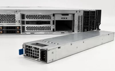
A CRPS module can match a general form factor yet fail to mate correctly with a specific cage or PDB. The controlled mechanical definition should include the body envelope, guide rails, insertion stop, latch, handle sweep, connector datum, permissible float, retention force and extraction clearance. The backplane position must allow full engagement without using the electrical connector as the mechanical stop.
Service clearance belongs in the same review. A module may be removable from an empty chassis but blocked in the rack by cable-management arms, rear doors, adjacent PDUs or bend radius of the power cord. If the operating procedure requires live replacement, the technician must be able to identify the failed module and remove it without disturbing the surviving feed or obstructing its airflow.
Airflow changes after a module is lost
Power conversion and backplane losses become heat inside a very small space. In normal operation, two module fans may contribute to the server’s rear airflow. After one module or fan becomes unavailable, the surviving converter dissipates more heat while the failed bay may become a leakage or recirculation path. A blanking feature, internal baffle or host fan response may therefore be part of the supported degraded state.
Thermal evidence should use the inlet condition at each module, not only the cold-aisle setpoint. Cable bundles, rear obstructions and exhaust recirculation can create a local inlet temperature different from the room measurement. The PDB also needs airflow: high-current isolation devices, shunts and connectors can heat even when the PSU casing remains within its own limit.
Specify an assembly rather than a generic backplane
A purchase or integration request should identify the exact CRPS modules, permitted revisions, cage, populated PDB, downstream harnesses or busbars, input arrangement, target host and required service state. It should state whether one or two modules are included and whether the quoted object has the isolation, sharing, standby and management functions assumed by the design. A bare PCB, populated board and complete cage assembly are different deliverables.
For a replacement in an existing server, the host manufacturer’s approved part and service documentation normally control the decision. For a new server design, the integrator must own the interface evidence and demonstrate the required behavior of the assembled path. In both cases, family-level CRPS terminology is a useful starting point, but the final configuration must be tied to the exact mating hardware.
A defensible CRPS 1+1 redundant power supply backplane design makes its limits visible. It names the failures that are covered, shows where isolation occurs, proves that one supported module can carry the required load, and follows that current through every shared component. That is the difference between two installed power supplies and a server power subsystem that can actually survive the intended single failure.