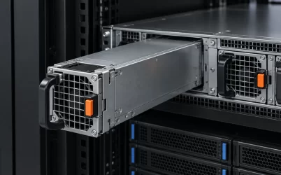
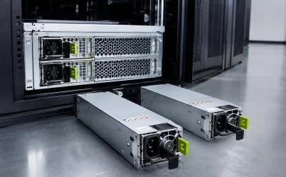
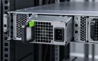
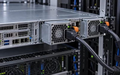
A low-profile AC-DC open frame power supply solves a mechanical problem first: the available vertical envelope is too small for a conventional enclosed unit. That constraint changes far more than board height. It affects airflow, touch protection, wiring clearance, insulation coordination, mounting, service access, and the evidence needed to demonstrate that the finished equipment is safe and dependable. A board that fits under a cover is not automatically suitable for the product around it.
The useful starting point is a complete integration boundary. Define the permitted height above and below the PCB, the enclosure material, airflow direction and volume, input connector location, output wiring, ambient temperature near the board, earth connection, accessible-service conditions, and applicable safety requirements. Select an open-frame supply only after those conditions are clear enough to compare a real documented model.
Quick answer: low profile means a system-level thermal and safety decision
Choose a low-profile AC-DC open frame PSU by matching its documented mechanical drawing and operating conditions to the host equipment, not merely by filtering catalog results by wattage and height. Verify the complete three-dimensional clearance, airflow at the supply, input and output wiring routes, mounting method, protective-earth scheme, isolation requirements, and derating information. A short board can create a difficult integration if a cover restricts convection, a cable crosses a high-voltage area, or a metal chassis changes the required clearance. The final product must be evaluated as an assembly.
The height budget includes more than the PCB
“Low profile” is frequently treated as a single maximum-height number. In practice, the tallest installed component, connector body, solder-side features, mounting hardware, wire bend radius, and enclosure features all consume vertical space. A drawing dimension may describe one location on the board rather than the clearance needed across the complete assembly. Record the full envelope with tolerances and specify whether the limit is above the component side, below the solder side, or between two enclosing surfaces.
Output connectors and input terminals deserve special attention. Their body height and wire exit direction may be more restrictive than magnetic components. Wires also require a controlled bend path; pressing a harness flat against a board can stress terminations or bring insulation too close to parts of the circuit that should remain separated. If an enclosure cover includes ribs, fasteners, shielding, or thermal pads, represent those features in the fit review rather than relying on a nominal flat plane.
Mechanical drawings support screening, but a physical fit check remains valuable for tight assemblies. Use a nonenergized sample or a representative mock-up to confirm insertion, fastening, cover closure, and service clearance. The review should identify which dimension is an assembly requirement and which belongs solely to the power supply manufacturer.
Convection assumptions often fail inside shallow equipment
Open-frame supplies may be specified for natural convection, forced air, or a defined combination of the two. Those operating conditions cannot be transferred automatically into a shallow sealed enclosure. A nearby cover can trap warm air over the board. A system fan can help, but only if its flow actually reaches the supply and is not diverted by drive cages, cable bundles, shielding, or structural members.
Map the thermal path through the finished product. Identify the air inlet, fan direction, restrictions, board orientation, high-loss components, and the point where temperature should be measured for qualification. Ambient air at the equipment intake may differ substantially from the temperature around a supply installed near processors, motors, batteries, or other heat sources. A product that operates acceptably on an open bench may reach a different internal condition once its covers and neighboring hardware are fitted.
Derating information should be read with its stated basis. It may depend on input voltage, airflow, mounting orientation, ambient temperature, altitude, or a prescribed distance from adjacent surfaces. Do not create a new derating curve from a visually similar board or from a single temperature reading. When the host conditions differ materially from published conditions, obtain manufacturer guidance or run an appropriately controlled validation of the complete equipment.
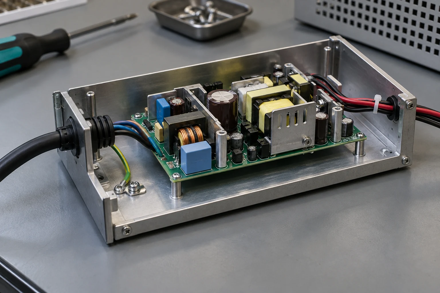
Keep mains-side boundaries visible in the layout review
An AC-DC open-frame PSU contains a mains-input region and an isolated output region. The product integrator must preserve the boundaries that make that design safe. Route low-voltage signal and output wiring so it does not cross or crowd input-side conductors. Ensure mounting screws, chassis features, conductive brackets, and cable restraints do not compromise the clearances expected by the supply documentation. Treat a protective earth connection as a defined electrical and mechanical path, not simply a green-and-yellow wire placed nearby.
Safety compliance belongs to the complete end product. A component’s approvals, markings, or test history can be important evidence, but they do not automatically approve an enclosure, wiring harness, medical or industrial end use, accessible surface, or installed service procedure. The applicable standard, product category, pollution environment, and accessibility conditions should be identified by the team responsible for the final equipment. Do not claim a certification or isolation performance for the assembly unless it has been verified for that assembly.
Input protection and transient behavior also need a system view. Upstream fusing, switches, inrush constraints, surge environment, grounding arrangement, and line connection must be designed according to the documented module requirements and the applicable equipment standard. Do not add or remove protective parts from a reference design based only on a nominal power rating.
Output wiring can defeat an otherwise good selection
The output side looks simpler because it is isolated and low voltage, but it can still determine whether the system works. Record nominal output requirements, allowed tolerance, load range, peak behavior, wire lengths, connector ratings, return paths, remote-sense requirements where applicable, and any downstream converters. A supply rated for the total load may still produce poor results if voltage drop in a harness leaves the load outside its permitted operating range.
Separate continuous load from transient demand. Motors, displays, storage devices, radios, and downstream capacitors can create startup or mode-change behavior that a steady-state calculation misses. The practical question is whether the exact supply and host circuit are documented or tested for the expected operating sequence. Adding arbitrary bulk capacitance or using an unverified connector adapter can change inrush, protection behavior, startup timing, and thermal stress.
Where multiple outputs or downstream rails are involved, define the dependency between them. A low-profile board may be one stage in a larger architecture rather than the source of every rail. Review enable sequencing, standby requirements, grounding, and fault handling with the system electronics team. This prevents a compact mechanical solution from becoming a difficult field failure.
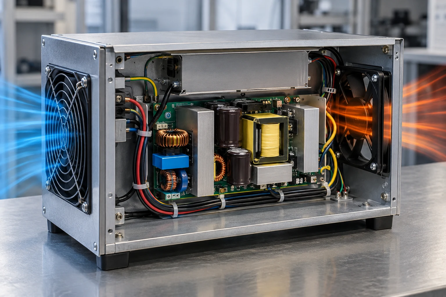
Mounting creates electrical and thermal consequences
Board mounting is not just a manufacturing detail. Standoff height, fastener torque, chassis material, insulation washers, vibration, and contact with thermal interfaces can affect clearances, mechanical stress, cooling, and EMI behavior. Use only mounting locations and hardware arrangements allowed by the component documentation. A conductive screw placed through an unintended location can create a safety problem; an insulating standoff in the wrong place can prevent a designed thermal path from working.
For vibration-prone industrial equipment, review retention of connectors, heavy components, harness strain relief, and the effects of repeated service. A field replacement procedure should state whether technicians remove the board, the enclosure, or a modular assembly, and which inspections are required after reinstallation. “Open frame” does not mean a board is automatically user-serviceable in the final product.
Build acceptance evidence around the installed product
Qualification is strongest when it follows the risks introduced by low height. Confirm mechanical clearance with the final enclosure. Measure or assess relevant thermal locations at representative operating states. Check input and output wiring, protective-earth continuity where required, startup behavior, and fault response. Review electromagnetic and safety compliance through the appropriate product process. Keep drawings, bill of materials references, and test records tied to the actual board revision and enclosure revision.
For related selection context, see industrial AC-DC power supply modules and open-frame DC-DC converters. These pages address different conversion boundaries; they should not be treated as interchangeable replacement instructions.
A compact review checklist
- Confirm the full component, connector, harness, and mounting envelope.
- Match actual enclosure airflow and temperature to documented operating conditions.
- Preserve mains-side and isolated-output boundaries in routing and mechanics.
- Verify input protection, earth path, output harness behavior, and load transitions.
- Evaluate the final product, not an uncovered board on a bench.
Document configuration control as part of the release. A change from one connector supplier, wire insulation type, fan curve, enclosure coating, or board revision can alter the conditions evaluated during qualification. The product record should make it possible to identify which supply revision was tested and which integration assumptions remain valid. That discipline is particularly useful when a compact product is manufactured over several years or serviced by teams who did not participate in its original design.
A low-profile AC-DC open-frame power supply can enable very compact equipment, but compactness narrows the margin for unsupported assumptions. The best selection is the one whose dimensions, cooling conditions, safety boundaries, and electrical behavior can be shown to fit the completed product with documented evidence.