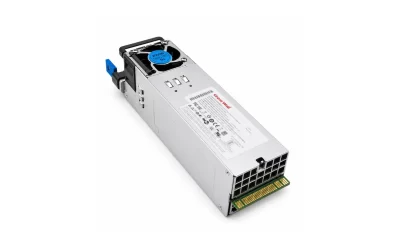
Redundant power supplies are wired as independent source paths that meet at a controlled common output—not simply as two positive leads twisted together. In an industrial DC cabinet, two compatible supplies may feed a specified redundancy module whose output serves the load. In a server, removable PSU modules normally mate with an engineered power distribution board or backplane that joins the outputs inside the host. Source isolation may reside inside each PSU, on that board, or elsewhere in the approved subsystem. The rack’s A and B input cords are a separate, upstream part of the arrangement. These two DC-output patterns answer the wiring question, but neither provides a universal pinout or permission to assemble an unapproved combination.
Locate where the two sources become one load path
A wiring drawing becomes much easier to read when its common node is identified. Before that node, the two sources have separate power paths and can be protected, controlled, or monitored independently. After it, the load sees one distribution path, although the system may divide that path into separately protected branches. Each source path needs reverse-current blocking before it can feed a failed source from the healthy bus. The common-bus junction and the physical isolation components need not occupy the same device.
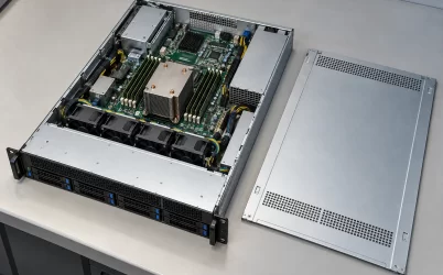
In the cabinet pattern, the junction is often a separate redundancy or isolation module. Each power supply’s output is routed to a distinct input of that module, and the module presents a controlled output to the DC load. The enclosure integrator can see and document those external links. In a server pattern, the meeting point is usually within the supplied chassis assembly: PSU cartridges engage a mating interface, and a PDB or equivalent host circuitry delivers the common bus to the motherboard and other load zones. An operator sees the AC cords or DC feeds outside the server, but not a set of arbitrary output wires to be joined in the rack.
“Two supplies connected to the same load” hides the fault mechanism. If a source’s output fails short, the other can feed the fault unless isolation blocks reverse current. If one source stops, the survivor needs sufficient capacity. If a downstream branch shorts after the common node, source redundancy may not keep other branches alive. The drawing should name each boundary rather than imply that a second PSU protects against every electrical failure.
Upstream feed separation does not replace output isolation. Independent rack PDUs can keep each PSU energized after one feed disappears, but they do not determine whether the modules share a DC bus safely. Conversely, output isolation can protect against one failed PSU while both external inputs remain on the same upstream source. These are different drawing layers.
In an industrial cabinet, the redundancy device is visible
Consider a control cabinet with a single DC load bus and two approved AC/DC supplies. The intended 1+1 arrangement has each supply capable of carrying the protected load within its documented conditions. Separate supply outputs approach the redundancy device, where each path is decoupled before the shared load connection. A manufacturer may implement that separation with diodes, controlled semiconductors, or another specified design. The cabinet designer should follow the exact supply and module documentation; the functional relationship is general, but terminal names, polarity arrangements, ratings and sensing connections are not.
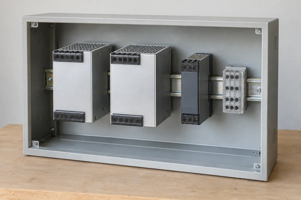
Rockwell Automation’s reference manual for one 1606 supply family shows this distinction concretely. It explains that simple parallel connection can leave a secondary-side short able to pull down both supplies, while its specified redundancy module provides decoupling. That is evidence for the failure mechanism and for one documented solution, not a wiring diagram that can be copied onto every industrial PSU. The manual’s model-specific current, temperature and terminal limits must remain attached to that model.
Why not join the outputs directly? Two nominally equal voltage regulators are rarely at precisely the same potential under load. The slightly higher source may carry most of the current; one supply can reach its current limit before the other contributes much. More seriously, a source-side short can turn an apparently redundant pair into a common outage. Some supplies are expressly designed for supported parallel operation, and some contain their own isolation or sharing functions. Their documentation governs what can be connected; the safe conclusion is not that all direct parallels are forbidden, but that a bare parallel symbol does not establish redundant fault behavior.
The return side deserves equal attention. A simplified drawing often shows only two positive paths converging at the redundancy device and one common return. Real modules may switch, sense, or route both conductors differently. A DC return is the normal current path; a protective-earth bond has another purpose. Their physical relationship must follow the equipment and installation design rather than being guessed from the symbol on an attractive marketing schematic. Alarm contacts or status outputs are not substitute load conductors either. They report loss of a path if the product supports that feature; they do not carry the protected load.
In a server, the mating assembly carries the output connections
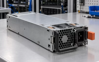
A removable server PSU is not normally wired into the motherboard by field-splicing output leads. Its output, return, standby and control functions meet a host-specific card-edge or other mating interface. A PDB or motherboard power assembly routes the resulting bus and may generate additional rails, isolate failed modules, monitor presence and coordinate insertion. The source path is a physical assembly, not merely a red wire from each PSU to a shared lug. Mechanical fit, contact geometry and the host’s supported electrical behavior matter as much as the line drawn between two boxes.
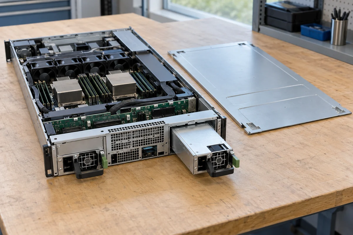
The Intel Server Board S2400BB Technical Product Specification, Revision 2.0, page 70 and Tables 21–22, provides a useful bounded example: for that platform, separate PDB power and control connectors can connect a redundant supply assembly to the board. That example does not provide a portable pinout for CRPS modules or for Powernexu products. Another chassis can integrate the functions differently or use another distribution interface. The exact host manual, compatible PSU list and PDB design determine what is already wired inside the machine. A technician should not treat two visually similar cartridges as interchangeable merely because both have rear AC sockets.
The internal common bus creates a separate fault boundary. Each PSU path needs a way to avoid back-feeding an unhealthy module, and the bus must remain within the host’s supported voltage behavior while a module leaves or joins. Output distribution then proceeds to CPU regulators, storage, accelerator connectors, fans and auxiliary circuits as the particular server requires. The server PDB architecture discussion examines those internal isolation and branch-protection functions in depth; the wiring distinction here is where the host-provided subsystem begins and where an external installer must stop.
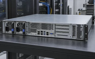
With a pre-engineered server, external cabling still matters, but it is upstream input wiring. One cord or DC feed reaches each PSU inlet according to the platform’s supported arrangement. Independent A/B sources may protect against loss of one upstream path when the facility actually keeps them separate and the surviving PSU can carry the server’s permitted load. That is different from inventing a new DC output connection between cartridges. The server’s redundancy setting, feed assignment and capacity have their own documentation; they cannot repair a missing source-isolation function or justify an unsupported module pair.
There is no universal connector pin map at this level. Server boards differ in power contacts, control pins, sense returns and management interfaces even within familiar packaging families. Only the exact platform’s drawings can answer that narrower question; an invented generic pinout may create a fault that a plausible power diagram conceals.
Sharing current is not the same job as blocking a fault
Two healthy supplies can be present without dividing the load evenly. Current-sharing control, where provided, nudges their output behavior so one module does not carry an unintended majority of demand. Fault isolation prevents an unpowered or shorted path from pulling down the shared bus. These functions interact, but they solve different problems. A redundancy module that blocks reverse current may not force equal current during ordinary operation; a share-control link cannot substitute for a source path that blocks a short.
That explains a common misconception about the visible wires. The cable or trace marked “share” on one manufacturer’s schematic may be a control signal, not a heavy-current conductor. Its voltage, reference and allowed connection are specific to the supported source family. The large output conductors carry power; the isolation stage determines how each source joins the bus. Server modules often manage these relationships through a mating board and platform logic rather than loose field wiring. Looking at one signal label and duplicating it on a different PSU family cannot establish compatibility.
Where a platform deliberately runs one supply as a hot spare, equal current is not even its normal goal. Where both units actively share, their percentages can move with load and operating policy. Whether redundant power supplies load balance in normal operation is a control-policy question; the wiring question is whether a defined failure leaves a viable, isolated path to the load. Two input meters need not display identical watts for that path to be redundant.
A fault changes the path, not merely the diagram color
Imagine the industrial cabinet’s first PSU loses AC input. Its DC output falls away. The approved redundancy device prevents the common load bus from discharging back through that inactive path, while the remaining source takes the defined load if it has sufficient capacity. A short on the first supply’s output is a harsher case: the isolation device must block a low-impedance fault rather than simply wait for a quiet source. If the load itself shorts after the junction, both supplies may see the same downstream event unless branch protection isolates it. These are three electrically different drawings, even though each begins with two power supplies.
Now consider a server. If one cartridge loses input, the host PDB or equivalent path should preserve the bus under its documented redundant configuration, and the management system may report degraded operation. If the cartridge’s output develops an internal fault, the supported power subsystem’s source-isolation arrangement must contain it, whether the blocking components are inside the module or elsewhere in the approved path. If the server has grown beyond one module’s supported capacity, neither clever wiring nor a healthy second inlet can make the one-module state sustainable. Those outcomes are conditional on the server’s design, not generic promises made by the word “redundant.”
A side-by-side sketch helps if it does not pretend to be an installable schematic. The industrial path shows two supplies entering an isolation device before one load bus. The server path shows approved cartridges mating with a PDB that feeds internal branches. Upstream A/B sources sit before both patterns; protective earth is outside the normal output-current loop. Mark the first common component. That communicates the fault boundary without fabricated connector pins or cable sizes.
Where a generic diagram must end
The broad answer is now precise: redundant supplies have separate input and conversion paths, then meet through a supported isolation/distribution point before the protected load. An industrial installation may make that point a separate redundancy module with externally visible DC links. A server typically joins the outputs through a PDB or backplane with a host-defined blind-mate interface; its isolation components can be located within the PSU modules or elsewhere in the approved subsystem. Upstream A/B feeds, output-current sharing, protective bonding and status wiring are related but distinct layers.
Physical connections beyond that abstraction come from the exact supply, module, server and facility documents. They define terminal identity, protection requirements, compatible modules and approved service work. The useful takeaway is where the electrical join occurs and which fault it must isolate—not a universal instruction to parallel arbitrary PSU outputs. A schematic that omits the independent paths, junction and source isolation has not explained the redundancy wiring.