A 24V industrial power supply can run a PLC steadily for hours, then the controller resets when a valve or relay operates. The nameplate watts may appear generous. That does not mean the supply is defective, and it does not mean a larger supply will cure the event. Coil energization can pull current through wiring shared with the electronics; coil de-energization releases stored magnetic energy into a path set by the switching and suppression circuit. Those are different events with different remedies. This is one specific industrial-control power problem, not a general guide to choosing a supply.
The useful first question is not simply “does the supply deliver 24V?” It is where the PLC sees its input voltage during each switching edge and how the coil’s current returns to the source. A converter can maintain its specified voltage at its own terminals while a shared cable segment or terminal produces a brief drop at the controller. Equally, a transient can disturb a digital output or sensor signal without the whole 24V rail falling. An installation has to distinguish those effects before blaming the converter.
Closing a coil circuit is a load step, not a flyback event
When the controller turns on a DC relay or solenoid, current begins to build in its winding. The coil’s resistance, inductance, driver, cable, and operating voltage determine the actual time course. It is misleading to assign every 24V coil the same inrush multiple. Some devices include economizers or electronic drivers that draw a different initial current from their holding current; a simple relay coil may behave differently. The manufacturer’s coil and driver data, not its voltage label alone, define the demand.
That rising current must leave the supply and return to it. If the PLC and coil share part of the positive feed or return, the coil’s changing current changes the voltage drop on that shared impedance. A controller can then see less voltage even if the power supply’s output terminals still look normal. A long field cable, small conductor, protective device, aging terminal, or common return can make a relatively modest coil step visible to sensitive electronics. A brief event may escape a slow handheld meter; a logged controller reset is not itself a measurement of the source’s output.
For a deliberately hypothetical illustration, suppose a shared round-trip segment has 0.25 ohm of resistance and the newly energized coil adds 2A through it. The incremental resistive drop is 0.5V. This is not a typical industrial coil or an allowed PLC-voltage limit; it simply shows why measuring at the converter and at the controller can give different answers during the same event. Contact resistance and dynamic behavior may add further effects. The relevant comparison is with the exact controller’s permitted input range and duration, including its own input capacitance and power-fail behavior.
Adding a freewheel diode across the coil does not remove this turn-on current. The diode normally does little while the coil is energized in the intended polarity. It addresses what happens when the driver opens. If the problem occurs only at turn-on, a discussion of flyback suppression alone has missed the load step and its distribution path. Source current limit, branch impedance, simultaneous coil activation, and controller supply hold-up deserve separate attention.
Opening the circuit exposes the coil’s stored energy
At turn-off, the magnetic field cannot disappear instantly. A coil carrying current stores energy, which in a simplified model is one-half times inductance times current squared. The actual assembly may include mechanical and electronic behavior beyond that ideal expression. If the driver suddenly interrupts current without a suitable path, the winding develops a voltage that tends to keep current flowing. The stress appears at the switching element and can couple into neighboring circuits. This is why a turn-off disturbance is not the same as a supply briefly lacking enough steady-state watts.
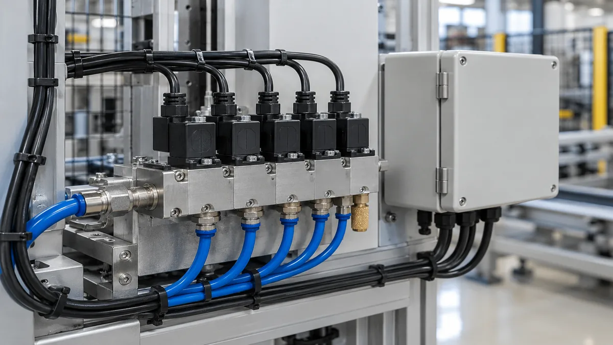
Omron’s original guidance on relay-coil surge countermeasures identifies back electromotive force at turn-off as a potential cause of semiconductor damage or malfunction. It describes suppression across a DC coil and warns that a surge-absorbing circuit can increase release time. That last point matters in control equipment: suppressing voltage is not free of functional consequences. The correct method depends on the actual relay, valve, driver, and required mechanical response.
A diode placed across an appropriate DC coil provides a local circulation path when the driver opens. That can greatly reduce the voltage imposed on the switching output. Current then decays through the winding and diode instead of being forced to stop abruptly. The armature or valve may therefore release later than it would with a higher-voltage clamp. A diode already built into a relay socket or load module changes the situation again; adding another component by habit can obscure what is actually installed. Polarity and component ratings must come from the equipment documentation, not from a generic internet wiring sketch.
Other approved suppression networks permit a different voltage and decay rate. A diode combined with a suitably selected Zener, a varistor, or a resistor-capacitor network may be used in designs whose driver and load documentation allow it. A higher permitted clamp voltage can make current decay faster, but it also increases the voltage the switching device must withstand. Those alternatives are not interchangeable plug-ins. A safety-related release time, an output transistor’s rating, and the load manufacturer’s instructions can rule out a convenient-looking suppressor. No universal clamp voltage or release-time number follows from the phrase “24V coil.”
The return path can make a local event look like a bad power supply
Imagine a cabinet with a PLC, several sensors, and an output module controlling a valve bank. The PLC and valve drivers are connected to the same 24V source. Whether they are truly isolated from each other’s current steps depends on where the wires join. Two branches drawn separately on a schematic can still share a length of undersized return cable or a single terminal before reaching the supply. Current in that common segment moves the electrical reference seen by the PLC and its I/O. A sensor input can change state even when the converter itself stays regulated.
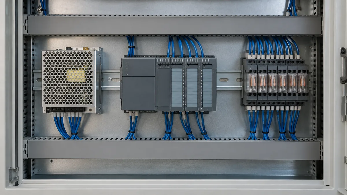
This is not necessarily “noise from the PSU.” The switching load, branch wiring, protective devices, and return layout may create the disturbance downstream of a healthy converter. Conversely, a supply entering current limit during simultaneous actuation can genuinely lose output regulation at its own terminals. Both mechanisms can occur in the same cabinet. Their locations differ, so observing only one voltage point can produce an overconfident diagnosis.
Separate protected branches for controller electronics and coils can reduce shared impedance, provided their returns and protection are arranged for the actual equipment. A separate converter may be justified when the load dynamics, uptime requirement, or sensitivity of the electronics make one rail impractical. But two boxes do not guarantee separation if their returns are recombined through the same weak path. Nor should an engineer simply raise the supply’s output setting to conceal a distant voltage drop: devices close to the source could then receive excessive voltage when the coil is off. The route of current matters more than the number of supplies in a drawing.
Local decoupling at the controller can bridge some short disturbances within the controller manufacturer’s limits. It is not a substitute for a sound distribution path, and adding capacitance can change startup current and protection behavior. A DC-UPS or buffer module serves a different purpose again: it may ride through a specified input interruption, but it does not automatically absorb a poorly suppressed coil transient on a connected branch. Before adding hardware, identify whether the observed event is a source collapse, a local wiring drop, a shifted return reference, or an interference problem at a signal input.
The switching output is a separate limit from the PSU rating
A control supply might be able to provide the coil’s continuous current while a PLC output cannot safely switch that inductive load. The output device has its own voltage, current, pulse, and surge ratings. Its manual may specify approved suppression and where it belongs. Suppression at the inductive device can protect an output or relay contact; it does not imply every output can drive every solenoid just because both are called 24V. The PSU’s overvoltage protection addresses particular source-side conditions, not every turn-off surge at a remote driver.
Built-in suppressors require careful interpretation. A relay base with an integrated diode is not the same component as an unsuppressed bare coil. Some modules include an LED, reverse-polarity protection, or another circuit in addition to suppression. The model’s data sheet describes those functions and their polarity requirements. If a service replacement changes the relay or socket variant, the release behavior may change without any change to the 24V power supply. This is particularly consequential where a valve’s de-energized position has a defined safety or process role. Do not treat a generic diode recommendation as authorization to change that behavior.
Two switching edges tell different stories
A practical account of the symptom should say whether the PLC resets as the coil energizes, as it releases, or only after repeated cycles. That timing narrows the physical mechanism. A turn-on reset may reflect current step, source limiting, or shared conductor drop. A turn-off reset points attention to inductive energy, switching-device stress, and coupling into power or signal wiring. A delayed failure after many cycles can indicate contact deterioration, heating, or a marginal connection rather than one instantaneous converter defect. Timing does not prove any one cause, but it prevents the two edges from being combined into a vague “power fluctuation.”
The observed location matters just as much. A converter whose output drops at its own terminals during the event has a different explanation from one that holds voltage while the PLC input falls. If the PLC supply remains within its documented limits yet one input changes state, inspect the affected signal circuit and its reference, not only the supply rail. Measurements on energized industrial cabinets require qualified personnel, appropriate instruments, and the site’s electrical-safety procedures. This article is a model for interpreting evidence, not a live probing or rewiring instruction.
Why the cure may change valve timing
The tempting response to a turn-off disturbance is to install the strongest-looking clamp. That can create another problem if it keeps a relay or solenoid energized longer than the process allows. Omron’s warning about release-time increase is not an obscure component detail: it connects electrical protection to the physical machine sequence. A door, brake, or valve may need a defined de-energized response. Its approved driver and suppression arrangement must meet that response as well as the electrical stress limit.
A different suppressor may shorten current decay at the price of greater voltage across the switching element. The safe trade-off is bounded by the actual output module and coil specifications. If the manufacturer’s assembly already includes a suppressor, the permitted field changes may be narrower still. These conditions belong to the specific machine design; a diagram that works for one relay family cannot be copied across outputs with different semiconductor ratings or required release behavior.
The same distinction keeps power-supply selection honest. Select a 24V source for the total continuous and transient load profile, permissible installation temperature, and documented protection behavior. Route the controller and coil currents so the former does not unknowingly carry the latter’s voltage drop. Then handle the coil’s turn-off energy with the approved driver and suppressor arrangement. A larger PSU might help if the existing source enters current limit on energization. It will not, by itself, correct a poorly located suppressor, an overstressed PLC output, or a shared return that moves the controller’s reference whenever a valve operates.