A server power distribution board (PDB) sits inside the server between the power-supply output and the hardware that consumes it. It accepts one or more incoming DC sources and carries power toward the motherboard, storage, accelerators, fans, and management circuits according to that platform’s design. It is not the rack power distribution unit that supplies AC to the server. Nor is it necessarily a universal replacement part: its connectors, protection, control paths, and mechanical shape belong to a particular chassis or compatible assembly. Understanding a PDB begins by following where power enters, which circuits can remain alive in standby, and where each output branch ends.
The board begins where PSU conversion ends
A rack PDU delivers an input feed to a server’s power supply. The PSU converts and regulates that input into the DC output required by the host. Only then does an internal distribution board, backplane, busbar assembly, or equivalent interconnect carry that output to the loads. Some systems combine several of these functions on one board; others place conversion, isolation, and distribution on separate assemblies. Calling all of them a “PDB” can hide the actual boundaries.
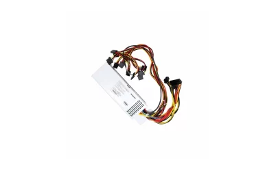
Start with the physical connectors. The upstream side may receive a blind-mate PSU module, a cable from a fixed supply, or a rack-sourced DC connection. The downstream side may use board-to-board contacts, bolted busbars, or harness connectors. The large conductors normally carry the main energy path. Smaller contacts may carry standby power, sense, identification, enable, status, or management signals. A photograph showing two PSUs and one green board does not prove which of those functions the board implements; the host documentation determines that.
This distinction matters when a server has power symptoms. If neither PSU receives its input, replacing an internal PDB will not restore the rack feed. If a PSU produces the expected output at its documented interface but a load never sees that bus, the interruption may lie at a mating contact, PDB path, branch protection device, or downstream harness. The location of the first missing voltage narrows the fault far more effectively than the label on the failed assembly.
Standby power can arrive while the main load remains off
A server that is plugged in but not running may still power its baseboard management controller, wake logic, or other designated standby circuits. On a platform with separate standby and primary outputs, the PDB must carry both without treating them as interchangeable branches. The management electronics can then observe a power-button request, identify a PSU, or coordinate startup before the high-current main bus is enabled. Other architectures assign more of this work to a motherboard or power shelf, so the actual sequence remains platform-specific.
In the conceptual illustration, the heavier path represents primary distribution and the smaller path represents a separate standby or control connection. It is not a pinout. A real board drawing must identify each rail, return, and signal before anyone probes or connects it. The practical point is that “the server is off” does not necessarily mean the board and its small connectors are unpowered.
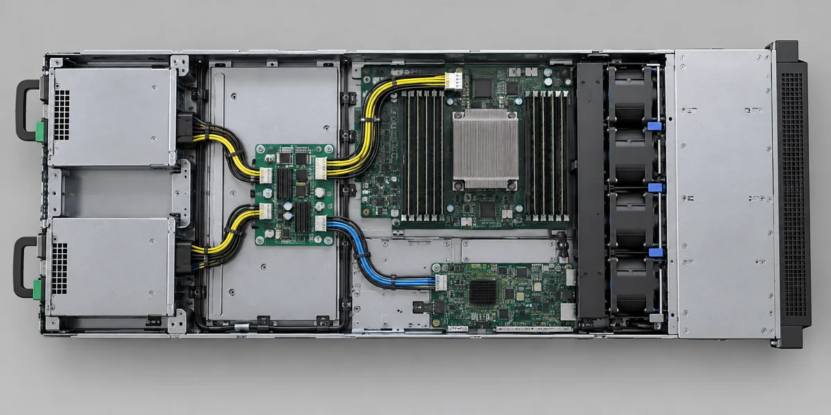
If the management controller responds but the host does not start, the standby route may be intact while the primary route, enable chain, or a downstream condition prevents startup. Conversely, a dead management interface does not by itself prove that the PSU’s main converter has failed. It could reflect loss of input, standby generation, the PDB’s standby path, a control connection, or the management board. Observations should be tied to known test points and the documented power sequence, not to a generic assumption that both paths rise together.
Keeping the two paths separate also explains why hot-plug behavior is more than pulling out a module. The platform must define what remains energized, what reports presence, and what happens to the shared bus when one source disappears. A drawing that shows only thick power conductors cannot answer those state questions.
One source bus can feed several different destinations
After the PDB receives regulated power, distribution becomes a topology problem rather than a simple single-wire connection. The motherboard may receive a high-current bus through a short board connector. Storage cages may be reached through a separate harness. Fans, pumps, or expansion hardware may connect through another branch or through a controller that regulates their operation. The PDB may split those routes directly, or it may hand the bus to a motherboard that performs part of the fan-out. There is no universal list of outputs for every server.
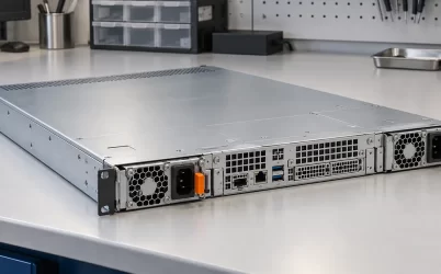
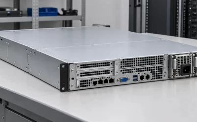
The pictured open server illustrates why physical endpoints matter. The PSU bay, board, and multiple destinations all appear in one chassis, but the photograph does not establish a wiring specification. A branch ending at a drive backplane has different service implications from one ending at the host processor board. If a storage bank loses power while the host continues operating, the shared PSU may still be healthy and the relevant question becomes where the storage branch diverges and what protects it.
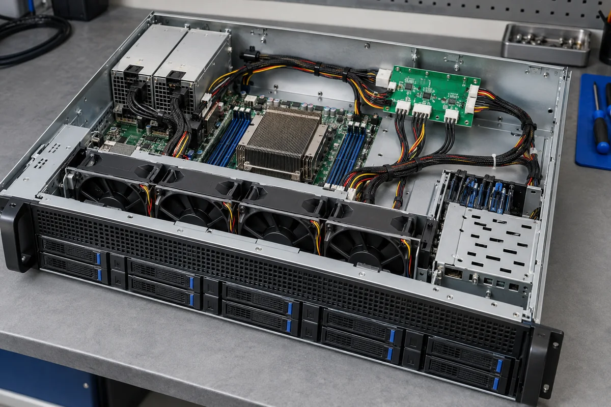
Distribution also creates several places where a small resistance becomes visible under load. A loose harness contact can heat while a lightly loaded standby connection beside it remains normal. A high-current busbar joint can cause a local voltage drop without changing the PSU’s reported output voltage at its own terminals. Those effects arise from current through real interfaces; they do not establish that a particular board is defective without measurements at the relevant points.
For a hypothetical 12 V branch carrying 20 A, a 5 milliohm path loss would be 0.1 V and 2 W at that path. The calculation is simply I × R for voltage drop and I² × R for dissipated heat. It is not a design allowance or claimed specification. Its value is explanatory: the branch current, not just the server’s aggregate wattage, determines where a particular connector or copper transition may become a thermal concern.
The PDB may distribute voltage without making the final load rails
A motherboard does not normally run its processors directly from the same bulk bus that arrives from a server PSU. Point-of-load regulators on the host board create the lower voltages required by silicon and memory. Therefore a PDB that carries a 12 V or 48 V distribution bus should not be described as supplying every chip at that voltage. In some architectures the PDB itself includes conversion or regulated auxiliary outputs; in others it is primarily an interconnect. The correct boundary is the actual design, not the acronym.
That distinction appears in the Open Compute Project M-PIC Base Specification, which describes alternative arrangements in which power may reach peripherals through a PDB or a host processor module and, in certain remote-distribution variants, assigns standby provision to the PDB. Those arrangements are examples within that specification, not universal rules for Powernexu products or every rack server. They demonstrate why “PDB output” must be attached to a named electrical boundary.
For an engineer reading a system drawing, the useful questions are specific. What source rail reaches the PDB? Which connectors carry that rail onward? Does a downstream board perform conversion before the load? Where is the voltage measured and controlled? If remote sense is present, which physical point does it regulate? These questions help distinguish a source problem from loss within distribution or at a point-of-load stage without assuming the PDB is an active converter.
Redundant sources do not make every load branch redundant
Two removable PSUs can feed a common distribution board, but the protected boundary depends on how the outputs are isolated and what a surviving source can carry. If one module fails, the remaining module must support the operating load under the relevant input and thermal conditions. A shared connector, unprotected common bus, or common downstream branch can still be a single point of failure. The presence of two modules does not make each cable, branch, or load regulator independent.
Some platforms place output isolation within each PSU; others put it on the PDB or coordinate it across both. Hot-swap controllers, ideal-diode devices, or other arrangements may be used, depending on the architecture. It is unsafe to look at a board and assert that it has a particular ORing stage without a schematic or verified product documentation. What matters functionally is whether a faulted or removed source can pull down the common bus and whether the surviving path remains within its limits.
Upstream feeds form a separate boundary. Two PSU modules plugged into the same rack PDU may tolerate one module failure while remaining exposed to loss of that single rack feed. Separate A/B feeds can reduce that exposure when the server and infrastructure support them, but they do not remove the server’s internal common components. The PDB is one of those common components in many chassis.
If the practical task is to design or qualify the board itself, the existing server power supply distribution board design article covers current-path resistance, connectors, isolation, and validation in detail. The distinction here is more basic: map the source and load boundaries first, then decide which failures the actual installed assembly is supposed to contain.
A branch fault and a source fault can look similar at the front panel
A dark drive bay, stopped fan group, or server shutdown is an outcome, not a diagnosis. A branch protection device might open because of a short downstream; a connector might lose contact; a local converter might enter protection; or the PSU might stop supplying the bus. Fault reporting may identify some of these cases, but management logs are limited by where the platform senses current and voltage. A PSU alarm can even be a consequence of an overloaded downstream path rather than the original cause.
Consider a host whose management controller remains reachable while all compute loads are off. That observation indicates some standby path is alive. It does not prove that the primary PSU output has reached the motherboard, nor that the PDB is faulty. The next useful evidence is the platform’s intended startup sequence and measured voltage at documented boundaries: PSU output, PDB input, relevant PDB branch, and downstream board. The first boundary that differs from expected behavior locates the problem region.
In a second case, the host boots but a drive cage is absent. Here the main bus already reaches at least part of the system. Investigation can move to the drive branch, its harness, its local converter or protection, and the backplane itself. Replacing both PSUs without checking that branch may add downtime without addressing the failure. A chassis with multiple load zones makes this separation particularly valuable because one healthy branch does not prove another is energized.
These examples are diagnostic reasoning, not instructions to probe a live server. Exposed mains or high-current DC hardware presents hazards, and service access and test points vary by model. Use the manufacturer’s service procedure and qualified personnel for live electrical work. The article’s point is to identify the correct physical boundary so the documented service method can be applied to it.
Trace the hardware that the actual chassis contains
For a replacement or integration question, an image of a vaguely similar PDB is not enough. The chassis revision, PSU family, mating connector, mounting position, harness destinations, and any control or standby connections must agree with the host documentation. A board can appear mechanically close yet put a required signal or high-current path on a different contact. Conversely, two assemblies that look different may be approved alternatives under an explicit platform part-number scheme. That judgment belongs to verified host and component records, not visual similarity.
A useful system diagram should therefore show actual endpoints rather than only a rectangle labeled PDB. Once the drawing distinguishes source, primary bus, standby path, branch destinations, and local regulators, the board’s role becomes concrete. It distributes power where the platform says it does; it does not inherit every function of the PSU, rack PDU, or motherboard simply because those parts sit nearby.