A “server power distribution board backplane” is not one standardized part. In one chassis, the phrase means the board that removable power supplies plug into. In another, a seller uses it for the distribution assembly behind that board. A drive backplane at the front of the same server is a different component: it mates with disks and receives a power branch from the distribution system, often alongside separate data connections. The useful question is which connectors the named board actually carries and where power travels after leaving the PSU. That distinction prevents a storage fault from being mistaken for a defective PSU docking board, or a visually similar replacement board from being treated as electrically interchangeable.
Three boards can sit on the same power path
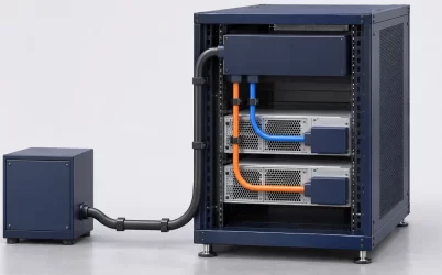
Imagine a rack server with two removable power modules at the rear and a row of hot-swappable drives at the front. The PSUs may slide into a cage and mate with an interposer, a power backplane, or contacts on a larger power distribution board (PDB). The PDB routes the resulting DC power toward the motherboard and branch loads. A separate drive backplane receives one of those branches and presents power and data connections to the drives. These boards may be separated by cables and a long section of chassis; none is automatically a substitute for another.
“Backplane” describes an interconnection role or physical position, not a universal circuit function. A manufacturer can use the term for the PSU docking assembly, the drive board, a midplane joining removable compute nodes, or a board that combines more than one role. Likewise, “PDB” can mean a populated PCB, a board-plus-cage assembly, or a named chassis service part. The exact boundaries come from the host’s parts list and wiring diagrams. Marketing photographs and secondhand listings often show only one side of the hardware.
The distinction is visible in a real manufacturer’s service structure. Lenovo’s ThinkSystem ST650 V2 power-cable guide identifies PDB connectors and separate drive-backplane power connectors linked by individual cables. That is one platform architecture, not a universal layout. It demonstrates why the drive backplane can be downstream of a PDB without being the PSU’s mating backplane.
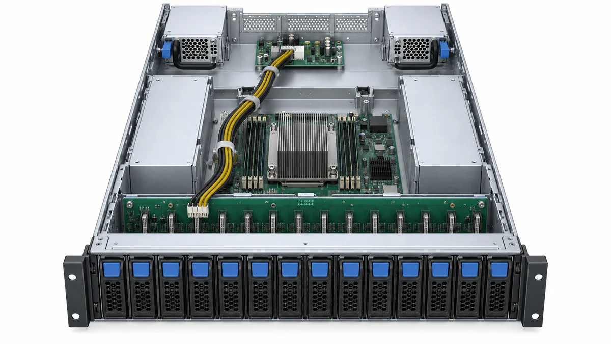
Names in a bill of materials can mislead. A replacement “power backplane” might include a cage but no PSU modules. A “hot-swap backplane” might be only a drive-bay board. A “PDB harness” might contain cables and no PCB. Identify the object and its mating connector before considering compatibility.
Where the removable PSU actually docks
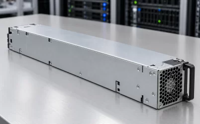
The docking board is the first server-side electrical interface encountered by a removable PSU. Its contacts may carry a high-current output and return, standby supply, control signals, identification, or management communication. Which functions exist, and which component implements them, vary by design. The module’s metal case and latch establish a mechanical insertion path; they do not specify the mating pin assignment or authorize using a visually similar board.
In a redundant chassis, two docking positions may feed a common distribution path. The source paths need the platform’s supported method of preventing one failed or unpowered module from dragging down the bus. Isolation may reside in a PSU, the PDB, or a coordinated combination. The docking board also has to survive the intended insertion and removal sequence. Contact engagement, enable timing, precharge or inrush control where used, and the host’s response to a missing module are functions of the specific interface. “Hot swap” on a PSU label does not make an arbitrary mating PCB safe for live replacement.
Module rails must bring the connector into full alignment without bending the board or loading a solder joint. A cage can accept the outer PSU body while misaligning its edge connection. Replacing only the PCB when cage guides remain damaged can reproduce a contact problem. An approved replacement should be defined by chassis and assembly revision, not only by slot count.
At a docking fault, symptoms may follow one bay. A module reports absent in that position but works in an approved alternate bay, or its output disappears under load after a poor contact heats. That pattern directs attention to the module-to-board interface. It does not prove the entire PDB is failed; a connector, latch, module, cable, control path, or sensor may be responsible. Service procedures should identify safe, documented tests rather than improvising a pin probe inside an energized bay.
The drive backplane takes power but has a separate job
A hot-swap drive backplane is usually defined by its drive slots, storage interface, and power connections. It lets installed drives connect to the server’s storage controller or host interface and receive the rails or locally converted power required by that design. Depending on the drive technology and chassis, the data side may include SAS, SATA, PCIe/NVMe, expanders, retimers, or sideband signals. Those details are platform-specific. A board that accepts several drive carriers is not automatically capable of combining PSU outputs just because it also carries substantial current.
The backplane’s incoming power connector is a downstream load connection. It can originate at the PDB, motherboard, or another power assembly. Some servers route separate branches to each drive board; others group several bays. Lenovo’s published drive-backplane power-cable route maps individual drive-backplane connectors to matching PDB connectors in one ThinkSystem configuration. Its cable lengths and labels do not transfer to another host.
The storage load is more than the sum of normal steady-state drive figures. A spinning disk may draw a higher current while starting than after reaching speed. A controller may stagger starts, or the platform may allow a defined simultaneous-start scenario. Solid-state drives have different behavior, and the relevant transient depends on the exact device and backplane. A high-current event can stress a branch connector or protection element even if the overall server PSU remains far below its nameplate output. The question belongs at the drive branch, not only at the main PSU rating.
Consider a hypothetical storage node that boots its management controller and processors but resets several drive bays when a group starts. This is not evidence that the PSU docking board is defective. The root cause could lie in a drive-backplane power connector, harness, local protection, shared return, storage controller sequencing, or a supply rail that sags under that particular transient. A separate branch measured healthy at idle can still fail under startup demand. The platform’s supported diagnostic points and event logs determine how to narrow the location safely.
The connecting harness is part of the electrical design
A cable from PDB to drive backplane is not generic wire. It has a particular mating family, keyed orientation, conductor count, wire size, current capability, and routing path. Some carry only power and return; others may include control conductors. The backplane may also use separate data cables. A convenient cable that physically fits can still put the wrong rail or return on a contact.
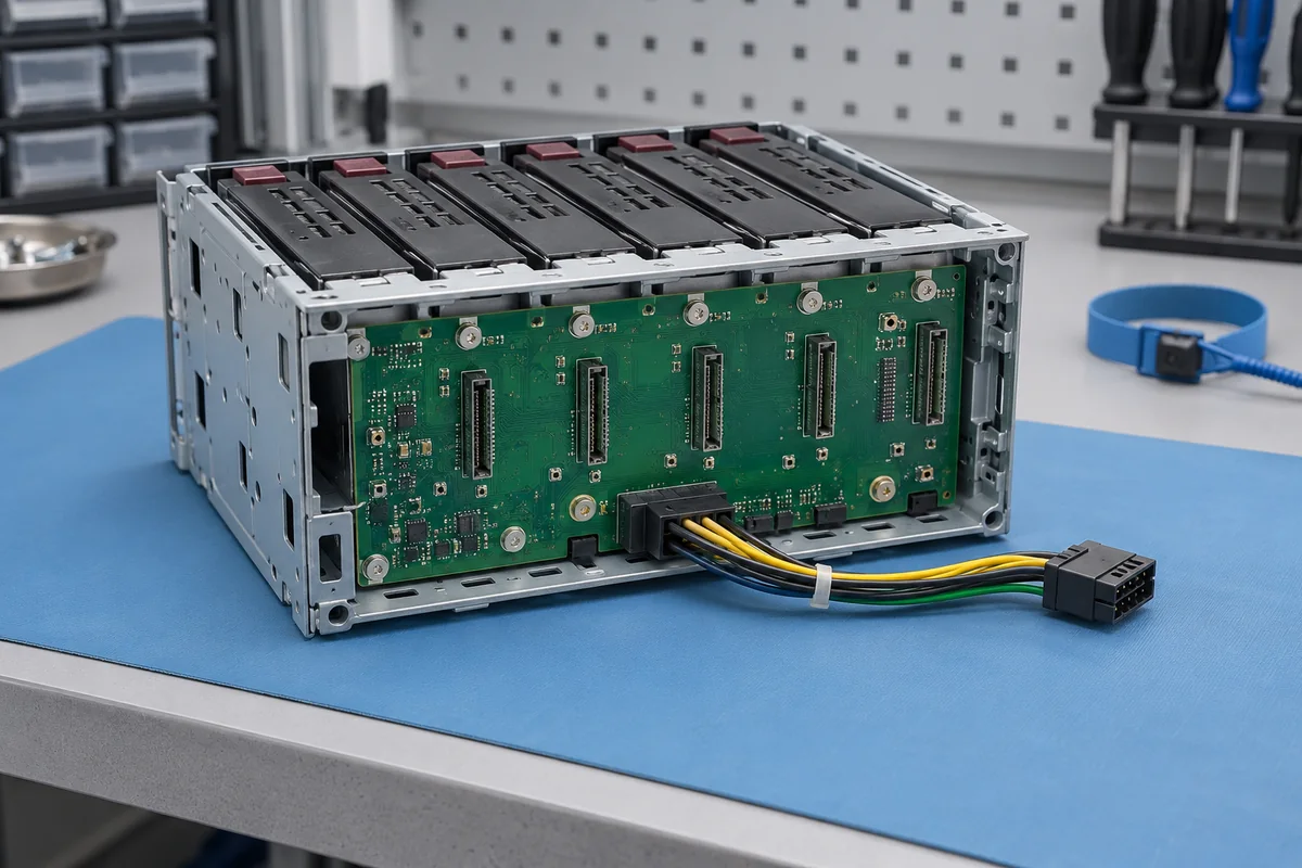
Current divides through the actual conductors and contacts, not through a diagram’s thick line. Connector resistance creates localized heat. A longer or undersized harness produces more voltage drop and may reduce the voltage available at the farthest drive bay during startup. Cable bundles can also obstruct the chassis airflow path when they are rerouted around a replacement board. Retainers and clips in the manufacturer’s service instructions keep the cable away from fans, sharp edges, and hot surfaces while preserving service access. They are part of the installation, not merely cosmetic cable management.
Tracing the harness answers a frequent spare-parts question: does the advertised PDB assembly include the lead to the drive cage? A quotation for a bare board may omit that lead; a complete chassis kit may include one selected for a specific bay layout. The difference matters when a damaged connector is on the cable rather than on either PCB. It also matters for a storage upgrade that adds another drive backplane. There must be an approved source connector, branch capacity, cable route, and supported controller connection for the new bays.
If a harness branches to more than one storage board, distinguish its aggregate current limit from each connector’s individual limit. A single PSU may have ample total output while one small connector sees too much current. Conversely, adding a second PSU to the same shared PDB does not automatically increase the permitted current of that storage branch. The physical harness and contact system remain the same unless the platform’s design changes.
Fault isolation follows the branch, not the name on the part
Three observations describe different regions of the server. If neither PSU is recognized and there is no standby service, investigate the input, docking, standby, and host-control path using the vendor’s diagnostic procedure. If the system stays on after one module is removed but a whole drive cage loses power, the source-combining path may be healthy while a storage branch is not. If one drive slot fails and neighboring slots continue working, the issue is more likely near that slot, carrier, local connector, or data path than at the common PSU interface. None of these patterns is a definitive component diagnosis on its own.
The PDB may include branch protection, sensing, or controllable outputs, but a photograph cannot establish those functions. A board that protects its motherboard path may use a different protection arrangement for drives. The management controller may observe PSU health while having little visibility into voltage at the remote end of a storage harness. A good PSU status therefore cannot prove that a front-bay backplane receives clean power. Likewise, a drive error can reflect data-link trouble while its power remains present.
When a failure occurs only during maintenance, the sequence is useful evidence. A PSU removal can transfer load to the surviving module and change current through the docking contacts and common PDB path. Removing a drive affects a local backplane slot and its storage protocol. Replacing a drive cage can disturb a shared power cable or a controller lead. Each event touches a different interface. Naming the interface and the changed operating state is more informative than writing “backplane fault” in a ticket.
Replacement scope is set by the server, not the PCB silhouette
A service replacement should preserve the platform’s approved board revision, PSU family, cage alignment, harness destinations, firmware expectations, and drive configuration. A drawing can show connector location and mounting, but it may not prove pin assignment, current limits, or behavior during a source fault. A parts catalog can show which board is supplied, but it may not establish that a bare secondhand board includes the necessary brackets and cables. These pieces of evidence answer different questions.
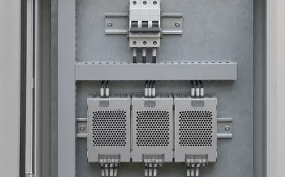
For a new design rather than a repair, make the boundary explicit in the mechanical and electrical architecture. Show the PSU docking interface, source-combining location, PDB branches, each storage-backplane input, and any downstream conversion. The existing server PDB design discussion covers copper, voltage drop, and source isolation in greater depth; the backplane question here is how those functions are physically divided between named assemblies. A board supplier cannot sensibly match a “server power backplane” request if the intended slot, source, load, and service scope remain unspecified.
One practical consequence is that two listings with nearly identical titles may both be accurate yet refer to different objects. A rear PSU interposer will not replace a front drive backplane. Do not assume a storage backplane combines redundant supplies; any integrated distribution or isolation function must be confirmed in the specific platform documentation. A PDB designed for one chassis revision may not connect to another revision’s cable set. The safe way to resolve the ambiguity is to place the candidate part on the actual source-to-load drawing and identify both mating sides. Once those endpoints are clear, the name becomes a convenience rather than a guess about function.