GW-PAH3000I-F is a Great Wall hot-swap power module listed for 3000 W output at 53.5 V, with published input ranges of 90–290 Vac and 188–400 Vdc. Its unusual purchasing question is the input architecture: a cabinet supplied from AC mains and one supplied from high-voltage DC may both be candidates, but the published ranges do not prove automatic source transfer, equal full-power output at every input, or compatibility with an existing shelf. The module belongs to Great Wall’s Hot Swap product group, not a demonstrated CRPS form factor. This article separates the verified rating from the cabinet-level electrical decisions that must be resolved before it is used as a source for a 53.5 V distribution bus.
What the manufacturer actually identifies
Great Wall’s Hot Swap product listing identifies GW-PAH3000I-F with 3000 W output, 53.5 V output voltage, 90–290 Vac input, 188–400 Vdc input, and CQC, CB, and CE entries. Powernexu’s GW-PAH3000I-F product page repeats those headline values and positions the unit for high-capacity DC cabinets and infrastructure equipment. These are useful identity and screening facts. Neither public page, as reviewed for this article, supplies a revision-controlled connector drawing, detailed load curve, full thermal derating table, or a documented source-transfer sequence.
The distinction matters because a 3000 W nameplate and a wide input range describe different properties. The former is an output rating under specified conditions; the latter identifies potential input operating regions. One cannot infer from their coexistence that the full 3000 W is available at 90 Vac, 188 Vdc, or maximum ambient temperature. Nor does the listing show whether a single physical connector accepts both source types, whether distinct versions exist, or whether an upstream transfer system selects one source. Ask for the exact ordered suffix, label, and technical manual when these details determine the installation.
Two input ranges, one output bus
The AC range, 90–290 Vac, covers a broad set of mains conditions. The separate 188–400 Vdc range is a high-voltage DC input; it is not a 48 V telecom battery input. A cabinet with a nominal 48 V battery plant could use this module only through an appropriate upstream conversion stage, if the complete design justified it. Connecting a low-voltage DC battery directly to an input specified to begin at 188 Vdc would be outside the published operating range. Conversely, a DC site bus inside the stated range still needs approved polarity, connector, isolation, protection, and grounding arrangements.
The ranges should also not be read as proof that AC and DC can be applied simultaneously. A manufacturer may publish two acceptable source types for a single input stage, or specify a particular wiring option or source selection arrangement. A public table does not reveal which applies here. If a site expects automatic movement between mains and a DC backup source, the transfer device, timing, interlocks, and permissible interruption must be described at the system level. The word “hot swap” describes module service behavior in a compatible host; it does not imply uninterrupted input-source switching.
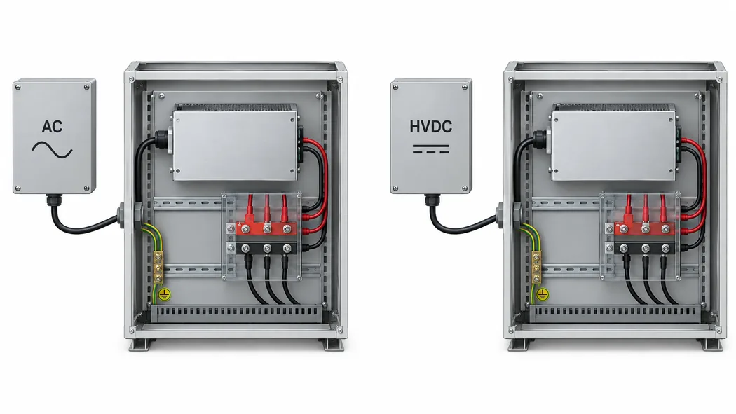
Even a source that stays inside the nominal voltage window may vary during startup, backup transitions, or fault recovery. A battery-backed DC distribution system can pass through charging, discharge, and transfer states. Whether GW-PAH3000I-F continues producing a regulated 53.5 V output through those states depends on limits and dynamics absent from the summary listing. For an uninterrupted load, obtain the module’s undervoltage behavior and hold-up or ride-through data, then compare them with the actual source waveform. A voltage-range comparison alone is insufficient for a continuity claim.
Reading 3000 W at 53.5 V
At the listed output voltage, 3000 W corresponds to approximately 56.1 A by simple division. This calculated current helps establish the scale of a busbar, cable, contact, and distribution-board review. It is not a separately published continuous-current specification and does not state what the module can deliver after input-voltage or ambient-temperature derating. A real load may also include startup surges, converter input-capacitor charging, and peak demand whose time profile matters more than an average wattage.
A 53.5 V output is close to, but not interchangeable by name with, every 48 V, 54 V, or 56 V system. The receiving converters have input-voltage tolerances; the distribution path has voltage drop; and any parallel supply has a defined output set point and sharing method. For example, if a downstream converter requires at least 52 V at its terminals, the margin between that threshold and a nominal 53.5 V source is 1.5 V before considering PSU tolerance and a loaded cable drop. This is an illustrative system constraint, not a published tolerance for GW-PAH3000I-F. It shows why the phrase “about 54 V” cannot replace the actual minimum and maximum bus-voltage specification.
At approximately 56 A, distribution resistance becomes a practical heat source. A hypothetical combined positive-and-return path of 10 milliohms would lose about 0.56 V and dissipate roughly 31 W at that current. Those are calculated examples, not measurements of this product. Busbars, mating contacts, board copper, fuse holders, and harnesses all contribute to the real path. A contact that becomes resistive may produce a local hot spot even though the PSU output remains within its own regulation window. The cabinet design therefore needs a loss and temperature budget beyond the module’s 3000 W rating.
For a power-conversion cabinet, the 53.5 V bus might feed several regulated downstream stages. The branch powers should be measured or estimated at their inputs, where their conversion losses are visible to the bus. Adding final load wattages alone can understate the source demand. A 700 W output converter operating at an assumed 90% efficiency would draw about 778 W from the bus under that example condition. Actual converter efficiency varies with load, temperature, and input voltage. The point is to avoid assigning the whole cabinet the 3000 W nameplate without accounting for intermediate stages.
When a hot-swap label is useful—and when it is not enough
Hot swapping can shorten service time when the host provides the required mating connector, guidance, latching, electrical sequencing, and capacity from other sources while one module is removed. It does not make any 3000 W module a universal plug-in replacement. The rack or cabinet must be designed around the actual module envelope and connector position. The public product summary does not give dimensions or a pinout for this model, so a visually similar bay or a neighboring Great Wall model is not evidence of mechanical interchangeability.
Inserting a power stage into an energized shelf creates a transition: input contacts engage, internal capacitors charge, control circuits start, and the output joins the bus according to the host design. The required sequencing, inrush limiting, precharge behavior, output isolation, and fault containment depend on the specific module and backplane. Those details should come from an approved interface specification. If a cabinet simply exposes power terminals and a removable module, the term “hot swap” on a catalog page does not by itself demonstrate safe extraction under load.
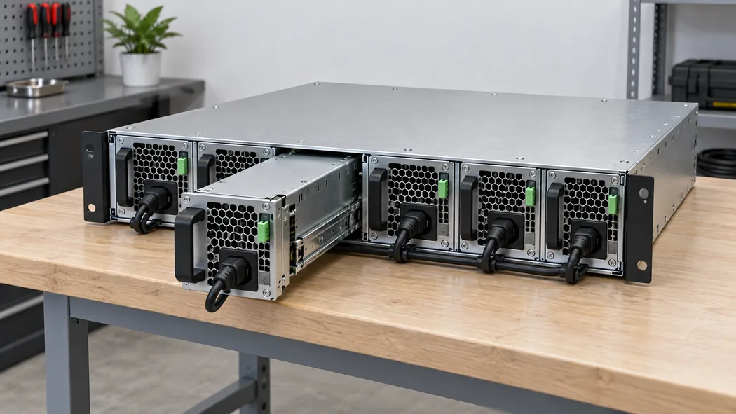
Consider a cabinet running from two modules with the goal of uninterrupted service after one is withdrawn. If each is nominally rated 3000 W, a 1+1 configuration has a maximum nameplate surviving capacity of one module, subject to its actual operating derating and the bus-sharing design. A continuous 4 kW load cannot be made failure-survivable simply by adding two 3 kW ratings together. Conversely, a cabinet intended for capacity combining may operate above one module’s rating while both are present, but removal then requires load shedding or another source. The service promise comes from the shelf architecture and load envelope, not the module label alone.
AC and high-voltage DC deployments ask different questions
An AC-powered cabinet may be attractive when local mains distribution is established and the PSU shelf can convert that feed to a common 53.5 V bus. The open questions are the real input-current curve, power factor, inrush, permitted protective device, connector, and full-load availability at the site’s low-line condition. A nominal 3000 W DC output also requires more than 3000 W at the input because conversion has losses. Without a verified efficiency value for this model under the intended condition, a precise branch-current or heat estimate would be speculative.
A high-voltage DC site may instead supply the PSU from a centralized rectifier, battery-backed bus, or other controlled distribution architecture. The 188–400 Vdc published window makes that possibility worth examining, but it does not specify the permitted grounding system, isolation arrangement, source impedance, DC input current, reverse-polarity tolerance, or protection coordination. It also says nothing about whether a particular battery system’s maximum charge voltage and minimum discharge voltage both remain inside the supported envelope. These are design questions for the exact site and controlled manufacturer documentation.
The two source types need not lead to the same thermal result. At lower input voltage, an input stage may carry more current for a given output power and may operate under a different thermal limit. A public maximum rating without a voltage-versus-power curve cannot answer whether an AC low-line installation and a high-voltage DC installation each sustain 3000 W continuously. Where high utilization is expected, request the applicable curve or a manufacturer-approved rating statement rather than extrapolating from the broadest input ranges.
Product boundaries that a catalog listing cannot settle
The Great Wall table and Powernexu listing establish a credible identity for a 3000 W, 53.5 V Hot Swap product, but there are several boundaries worth keeping explicit in a specification. Neither page proves a CRPS mechanical envelope or a standardized server backplane interface. Neither provides a public sharing protocol, telemetry map, standby rail, output ripple limit, overload timing, hold-up time, or allowed parallel combination. Similar-looking server power modules may differ in all of these ways.
These missing details have different consequences in different applications. A DC cabinet designer may choose a backplane around the module once the documents are supplied. A maintenance purchaser has less freedom because the shelf is already installed; a deviation in width, latch geometry, or control pins can invalidate a replacement. The same product listing can support initial sourcing in both cases, but it cannot close either design by itself.
Where GW-PAH3000I-F fits as a candidate
The strongest preliminary use case is a serviceable 53.5 V source for a cabinet or infrastructure platform whose source system can provide one of the published input types and whose downstream distribution is designed around the module’s actual interface. The 3000 W rating puts the output in a range where bus losses, branch conversion, and failure-survivable capacity are consequential. The high-voltage DC input range differentiates this model from a straightforward AC-only server module and may matter in a facility that already distributes high-voltage DC.
The model is a poor assumption for a conventional 12 V server bay or a nominal 48 V battery input without additional system conversion and verified compatibility. Likewise, it should not be introduced as a drop-in CRPS replacement on the strength of the Hot Swap category label. If the requirement is specifically a 53.5 V, 3000 W module with AC or high-voltage DC source potential, the public records justify a technical inquiry. The next document should be the exact manufacturer’s datasheet and interface drawing for GW-PAH3000I-F, followed by the host shelf requirements and input-source profile.
That boundary is useful rather than restrictive. The publicly verified facts establish what to ask for: a 53.5 V output path, a roughly 56 A full-power scale, two distinct published input windows, and a serviceable module category. The unresolved facts identify where an integration could fail: low-line output capacity, source switching behavior, DC protection, mechanical fit, hot-swap sequencing, and bus tolerance. Resolving those points against the exact cabinet turns GW-PAH3000I-F from a plausible catalog match into a defensible power-system component.