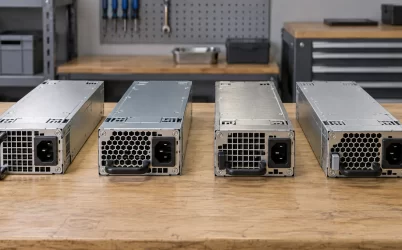
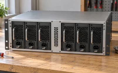
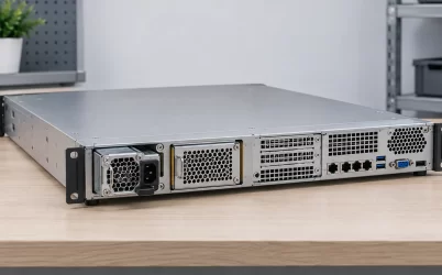
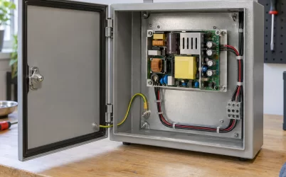
CRPS2700T2 is a Great Wall 2700 W Titanium CRPS module with a +12 V main output and +12 VSB / 3 A standby output. The useful question for a 12 V server is how much current its power path can carry at the installed input voltage, not whether the 2700 W label looks sufficient. Great Wall lists three main-output currents—98.4 A, 205 A, and 221.4 A—without assigning conditions to each on its public page. A separate 80 PLUS report confirms efficient operation of one sample at 230 V, but does not resolve low-line output capacity or chassis compatibility. This article separates those kinds of evidence so a buyer can make a defensible capacity comparison.
Read the three 12 V figures as distinct limits
The CRPS2700T2 product listing gives a 2700 W class rating, a 90–264 VAC or 180–320 VDC input range, and a main-output line containing 98.4 A, 205 A, and 221.4 A. The original manufacturer table confirms those entries. It does not label them by input band, ambient temperature, time duration, or hardware revision. They describe reported output-current points, not three independent +12 V rails whose ratings can be summed. The +12 VSB / 3 A output is separately identified for standby service.
Multiplication helps expose the scale: at a nominal 12 V, the three current values correspond to approximately 1181 W, 2460 W, and 2657 W. None is exactly 2700 W. That discrepancy does not prove an error. Output set point, tolerance, combined-output conventions, and the way a manufacturer names a power class may affect the arithmetic. The public table does not supply enough context to choose among those explanations. In particular, assigning 98.4 A to low-line input may be plausible, but it is still an inference until a revision-specific document says so.
This distinction matters for a 200 A server. Its nominal main-bus demand is approximately 2400 W, below the product’s headline rating and below two published current points, yet far above 98.4 A. The same server could be within one documented condition and outside another. A purchasing request that says only “2700 W CRPS” misses the parameter that actually constrains the build. Request the applicable main-output current versus AC or DC input, temperature, and duration. State the worst permitted feed at the PSU inlet, not merely the facility’s nominal service voltage.
What the independent efficiency report proves
An 80 PLUS verification report for CRPS2700T2 identifies Great Wall Power Supply Technology, model CRPS2700T2, a 2700 W rated output, and a test date of January 26, 2026. It records testing at nominal 230 V and 60 Hz. The report lists 96.29% efficiency at its 50% load point and 94.18% at its full-load point. Those are measured outcomes for the tested sample and conditions, rather than a constant efficiency that should be applied to every installation.
The full-load row is particularly useful because it records approximately 2850.52 W input and 2684.68 W output. Their difference is roughly 165.84 W in that test. At the 50% row, approximately 1401.17 W enters and 1349.25 W leaves, a difference of about 51.92 W. These numbers are not a system heat map: the report notes that fan power is excluded from its efficiency calculation, with external fan power applied. Nor do they establish how a production server behaves at 120 V, with a particular fan strategy, at a hotter inlet, or at a different mix of standby and main loads.
The report also gives a 5% point of 87.77%, a 10% point of 93.29%, and a 20% point of 96.13%. The shape matters more than choosing one percentage for a spreadsheet. A lightly utilized module can operate at a different conversion efficiency from one near its full rated condition. For a redundant pair, each module’s normal share may be quite different from the load on the surviving module after a failure. Facility input forecasts should use the actual operating points, or measured rack input power where available, rather than multiply every load by the report’s 50% value.
Certification supports a claim about the defined test program. It does not approve a blind-mate connector, a distribution board, or a particular server’s power budget. The 80 PLUS PDF has a pictured sample and a report ID, but the procurement team still needs the ordered revision’s label and current certification evidence. Great Wall’s public list also names several regional marks; those entries should be checked against the exact unit and destination market instead of copied wholesale into a system compliance declaration.
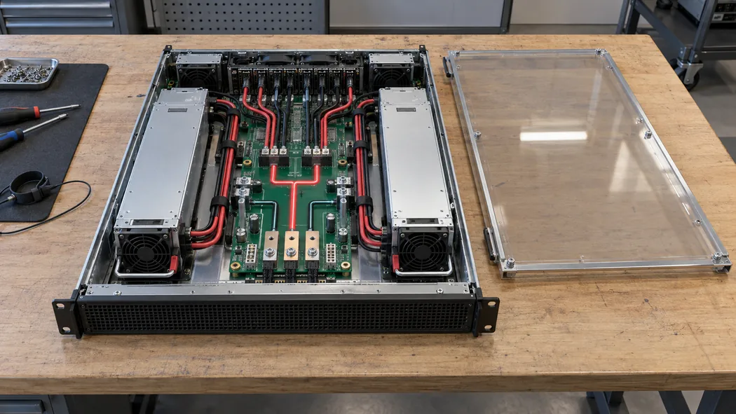
Locate the 12 V bottleneck inside the server
At approximately 200 A, a 12 V bus is as much a distribution problem as a converter problem. A hypothetical server may have 85 A allocated to accelerators, 55 A to processors and memory conversion, 35 A to storage and fans, and 25 A to other board loads. Those example figures total 200 A; they are not a CRPS2700T2 test or a recommendation for any host. The actual budget should use the power drawn at the common 12 V input to each branch, including conversion losses, and distinguish sustained demand from short excursions.
At the module interface, current passes through mating contacts before it reaches a board or busbar. Downstream it may cross copper planes, protection devices, connectors, harnesses, and local converters. A single 200 A total does not tell the integrator whether one branch contact is carrying 20 A too much. Identify each path, its current rating, and its thermal environment. Contact resistance turns current into localized heat; a small increase in resistance can become significant when current is high. Measurement at the PSU output alone can miss voltage drop at a remote load, while a board temperature sensor may miss a warm contact.
Great Wall publishes a 185 × 73.5 × 40 mm enclosure and FR airflow for CRPS2700T2. The shared envelope with other CRPS models helps screen bay geometry, but it gives no model-specific pinout, insertion sequence, connector current rating, latch detail, firmware approval, or host compatibility list. A module that slides into a bay can still leave the server with a mismatched mating interface. Obtain a drawing for the ordered revision and compare it with the host’s approved PSU assembly. A completed installation should not depend on the technician recognizing a product by its front handle alone.
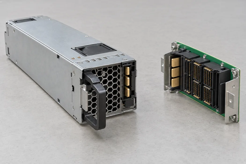
The separate standby rail introduces another boundary. The listed +12 VSB / 3 A can support host control functions only when the host’s standby architecture and timing agree with the supply. Its nominal arithmetic ceiling is 36 W, but the public page does not say whether and how standby power is included in the 2700 W aggregate rating. It also does not publish a model-specific enable, presence, or management pin map. Those interfaces must be resolved before proposing a replacement in a running server. A successful main-output load test cannot compensate for a controller that cannot identify or sequence the module.
Compare the 2700 T2 with its nearest alternatives
The closest names create two different comparison traps. CRPS2700TS5 shares the 2700 W class but has a +54 V main output, while CRPS3200T2 and CRPS3600T2 share the +12 V architecture and the listed 185 × 73.5 × 40 mm envelope. The TS5 is not a 12 V substitute; its bus voltage calls for a different distribution and downstream conversion scheme. A product-family suffix therefore matters more than the common 2700 digits. Mechanical resemblance cannot bridge an output-architecture difference.
Moving upward within the 12 V T2 family is a capacity question. The public Great Wall tables list CRPS3200T2 at 3200 W and CRPS3600T2 at 3600 W. They also publish multiple 12 V current figures for each, again without the operating-condition mapping in the summary table. A 2700 W module can be appropriate where the host’s documented single-module demand and operating conditions fit it. Selecting 3200 W or 3600 W purely because those numbers are larger does not increase a connector, PDB, rack feed, or chassis cooling limit. Conversely, a 2700 W unit should not be kept for a platform whose supported load exceeds its applicable current point.
The useful comparison uses the same assumptions on every candidate: exact model revision; minimum AC or DC input at the module; inlet temperature; continuous main current; allowed short-duration excursions; combined standby allocation; and the host’s supported assembly list. Only then does a wattage difference describe usable headroom. If the server vendor has an approved PSU spare list, it should control service substitution even when a third-party module has matching broad specifications. Where no approved list exists, the project becomes an integration exercise requiring drawings and tests rather than a catalog choice.
Understand the feed before assigning protected capacity
In a two-bay 1+1 server, ordinary operation may split current between modules. The relevant protected capacity is what one remaining module can deliver after the other has failed or been removed, under the worst supported feed. If the server draws 190 A continuously and each module carries about 95 A normally, failure of one unit asks the survivor to carry approximately 190 A. That hypothetical case is below Great Wall’s 205 A and 221.4 A entries but above 98.4 A. Until those entries are mapped to the installed feed and thermal condition, the protected-capacity claim remains unresolved.
Keep the failure event distinct from the settled load. A sudden transfer can cause a short current rise or output-voltage dip; the permissible duration and response require the host and PSU integration documents. A software power cap may later reduce CPU or accelerator draw, but the electrical path must survive the time before that cap acts. The public product table does not specify a failover waveform, current-sharing method, ORing topology, or host telemetry behavior. Avoid filling those gaps from another CRPS model’s manual.
A broad 90–264 VAC input range identifies where the product may accept AC. It does not say that 2700 W output is available from 90 V through 264 V. The independent report tests at 230 V; it does not provide a low-line output derating curve. The same gap exists for the listed 180–320 VDC input range. Use the actual input at the module terminals, including expected sag and transfer conditions, to select the matching manufacturer rating. Facility power planners must also compare the supply’s maximum input current, inlet hardware, cords, PDU outlet, and branch protection with the intended load. The public summary alone does not give a complete circuit-design basis.
The published 0–55 °C operating range is an envelope, not a statement that every listed current remains available at a 55 °C inlet. The manufacturer’s FR airflow designation should be reconciled with the host flow path. Required airflow and temperature derating belong in the revision-specific datasheet.
Turn the evidence into an orderable specification
For CRPS2700T2, a concise procurement record should attach three distinct artifacts. First is the exact model and revision identity, supported by a label photograph or part-number record. Second is the manufacturer’s current-limit table that maps the 98.4 A, 205 A, and 221.4 A figures to their conditions. Third is the host’s interface approval or, for a new design, its drawing and electrical requirements. The 80 PLUS report adds independently measured efficiency evidence at 230 V, while leaving those capacity and interface questions open.
Write the server load in amperes on its 12 V bus as well as watts. Include the highest steady demand and the excursions that the platform is expected to tolerate. Specify whether the load has to survive a module removal, a failed rack feed, or neither. This makes the relevant current point and failure path explicit. If the condition mapping or host approval cannot be obtained, keep the power-capability claim provisional. The product may be promising, but a 2700 W nameplate and a Titanium certificate cannot resolve the missing operating boundary for a specific server.