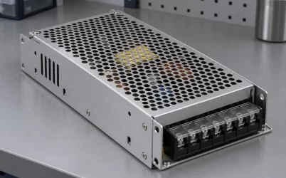
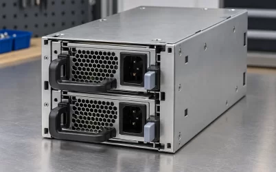
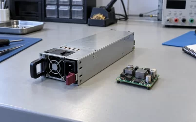
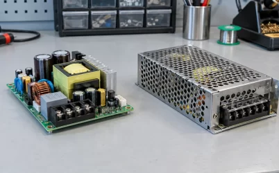
G1179-1600WNA is listed as a 1600 W member of Gospower’s G1179 2U, 1+1 power distribution board family. It is a backplane and system distribution assembly, not a standalone AC-to-DC CRPS module. The distinction matters when replacing a failed server power assembly: a matching power rating cannot establish the PSU mating interface, host connector map, or the loads allowed on each output. Powernexu lists 265 × 77 × 84 mm for the exact suffix; a Gospower family listing gives a different nominal envelope. Treat the board revision and its controlled drawing as the decisive references for fit and wiring.
What the G1179 name establishes, and what the suffix does not
Gospower identifies G1179 as a 2U, 1+1 PDB series. Its description says a PDB backplane can combine with 185 mm CRPS power supplies to form a redundant system and can provide standard ATX or customized outputs. A separate manufacturer family listing includes 1600 W among the available power classes. These statements establish the product category and intended system architecture. They do not identify a particular CRPS part number approved for G1179-1600WNA, a pin assignment, or a simultaneous output loading table.
The Powernexu G1179-1600WNA product listing gives the exact suffix, 1600 W headline rating, 2U PDB category, and individual rail entries. A reader can use that page to identify the item for an inquiry. It should not be read as a complete assembly drawing. The catalog’s 90–264 V input field most plausibly describes the compatible AC-powered system configuration, because a PDB downstream of a CRPS normally receives converted DC from its modules. That interpretation is an engineering inference, not a published pinout for this board. Ask for the input-side interface document before connecting any source.
The suffix is also not a universal fit code. Two assemblies can share G1179 family branding and 2U height while differing in connector count, output harness, board revision, power tier, or mechanical mounting. Even the manufacturer’s broad statement about 185 mm CRPS does not authorize every supply of that length. A module must mate mechanically and electrically, provide appropriate standby and control signals, and be approved with the backplane’s current path. Likewise, the fact that a host accepts an ATX-like connector does not prove the entire harness and control scheme match this PDB.
At 1600 W, each branch needs its own load account
Powernexu’s published entry lists +12 V at 132 A, +5 V at 25 A, +3.3 V at 25 A, -12 V at 0.5 A, and +5 V standby at 3 A. These are catalog rail-current entries, not an explicitly stated simultaneous-load matrix. Multiplying the 12 V entry by 132 A yields 1584 W at nominal voltage, already close to the 1600 W headline. Multiplying and then adding all the other listed maxima would exceed that headline. The useful conclusion is that maximum entries cannot safely be treated as independent, concurrent budgets without the manufacturer’s combined-power conditions.
That distinction changes how a 2U server or storage designer partitions loads. Processor and accelerator converters may draw heavily from 12 V; legacy or peripheral branches may use 5 V or 3.3 V; management electronics may remain on standby power when the main outputs are off. The PDB may pass some rails through, generate others locally, or use a particular converter arrangement. Public information for the exact suffix does not establish which path applies. A current number on a catalog page cannot replace a rail-generation schematic, connector current rating, and load-combination table for the ordered revision.
Consider an illustrative host that requires 120 A on its main 12 V branch during a defined peak interval. Nominal arithmetic gives 1440 W on that branch alone. Whether that host is supported depends on peak duration, allowable voltage variation, connector and copper temperatures, the remaining active rails, and the installed module’s capability at the actual input. This example is a method for framing a question, not a claim that G1179-1600WNA is approved for that load. A procurement request should state continuous and transient current on every rail rather than offer a single total wattage.
A second issue is the location of the current measurement. A PSU label may state output current at its own connector, while the motherboard receives power after contacts, board traces, protective devices, and cables. Loss in that path can change voltage at the load and create local heating even when the module is within its rating. At this current class, connector contact resistance, harness wire size, and the number of populated pins are meaningful design variables. The public listing does not disclose those details, so it cannot support a replacement decision by arithmetic alone.
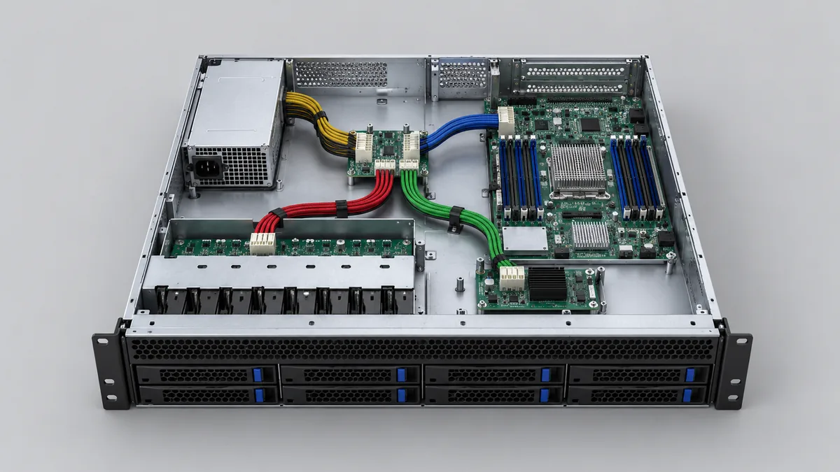
Interpret the 1+1 claim at the surviving-module boundary
A 1+1 system generally has two installed conversion modules with one able to support the protected load after the other becomes unavailable. The protected capacity is therefore constrained by the surviving module and by the PDB’s distribution path; it is not the sum of both module nameplates. If the modules share load during ordinary operation, a failure can shift current quickly to the remaining unit. Its output rating must be valid at the surviving AC or DC feed, ambient and airflow conditions, and the expected host load profile.
The G1179 family description supports its use in a redundant CRPS assembly. It does not publish the exact -1600WNA module pairing, current-sharing implementation, isolation device, or transfer behavior. Those details need documentation specific to the board and selected modules. A nominal 1600 W module may have a lower permissible output on a low-line AC feed; the actual derating depends on its data sheet. If a rack has two power feeds, each feed’s voltage and circuit capacity must be checked for the post-failure case. The board’s 90–264 V listing alone does not establish protected capacity throughout that input range.
For a telecom edge cabinet, the consequence may be especially practical: a site can have an adequate combined power budget but an unsuitable surviving feed during a maintenance window. For a storage system, a drive spin-up or recovery event can coincide with the loss of one module. These are example failure scenarios, not documented G1179 field results. They illustrate why an approved module pair, site feed, and host load envelope must be identified as one configuration.
The published dimensions describe different boundaries
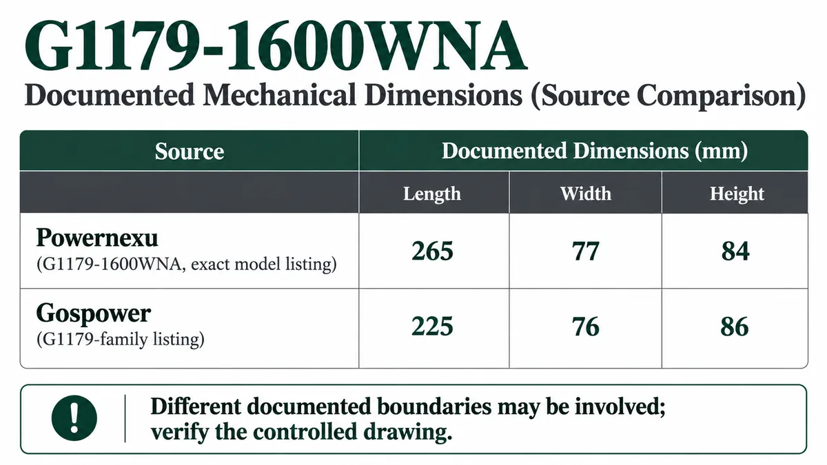
Powernexu lists G1179-1600WNA at 265 × 77 × 84 mm. A Gospower G1179 family listing gives approximately 225 × 76 × 86 mm. Neither page supplies a clearly labeled, revision-controlled drawing that reconciles the apparent difference. The measurements may describe different system boundaries, mounting features, or assemblies; the available pages do not prove the reason. It would be unsound to average them or silently substitute the family value for the exact suffix.
For a 2U chassis, the difference is not just a question of whether a rectangular envelope clears the lid. The module insertion line must land on the PDB connector. Board supports, screw holes, guide rails, rear-panel apertures, extraction handles, airflow seals, and host-side harness bends occupy specific locations. If the catalog length includes a feature that the family dimension excludes, even a seemingly larger bay may still place the mating plane incorrectly.
A controlled drawing should mark the mechanical datum, mounting-hole centers, PSU mating-plane location, connector keep-out zones, and overall installed depth. It should also identify the specific board and assembly revision. A side-by-side comparison against the existing chassis drawing is more useful than a single outside measurement. For a replacement order, record the old board’s label and revision, photograph both faces and connectors, and compare the manufacturer’s drawings before assuming two 2U G1179 products interchange.
Follow the output topology into the host harness
The page’s mixture of +12 V, +5 V, +3.3 V, -12 V, and standby entries suggests a multi-rail host interface, but it does not tell an installer which connector carries each rail. The manufacturer says standard ATX output or a customized output can be supplied at the family level. That choice can change a board’s exact output assembly even when the same headline rating appears in a catalog. Connector shape alone is a poor guide: keying, pin order, sense wires, power-good behavior, enable signals, and return paths all matter.
Start the host-side mapping with the actual motherboard and peripheral power requirements. Identify the connector part numbers, pin assignments, number of contacts used per high-current rail, cable lengths, and branch protection. Then align each requirement with the controlled G1179-1600WNA drawing. If the host expects a particular standby rail during soft-off, establish where that rail originates and how it behaves when either CRPS module is removed. If a customized harness is ordered, that configuration should be represented by a distinct drawing or approved assembly identifier, not by an informal description of the same suffix.
Care is needed when replacing a PDB inside an existing machine. An apparent match in external size and output labels can hide a different sense or control contact. Reversing a standby or signaling pin can cause failure before the main load is applied. A benign open circuit can be equally disruptive if it prevents module enable or fault reporting. Because the public suffix page does not publish a pin map, its rail list is useful for initial screening but cannot authorize a plug-in swap.
Resolve the document conflict before ordering the assembly
The public evidence is sufficient to classify G1179-1600WNA as a 1600 W-class listing within a 2U PDB family. It is insufficient to fix the exact electrical and mechanical interface. That difference determines the most useful next request: obtain the suffix-specific specification, board revision, outline drawing, approved CRPS list, connector and pin map, and combined rail-load limits. The request should also state the host chassis and motherboard identifiers so the supplier can evaluate a real assembly rather than a wattage label.
The apparent 225 versus 265 mm length difference deserves an explicit written answer. Ask what each dimension includes, the datum used, and whether the published Powernexu dimensions represent a complete redundant assembly rather than a bare backplane. Ask the same for the 77 versus 76 mm width and 84 versus 86 mm height, which could affect guides or lid clearance. Neither source identifies a tolerance or mechanical revision in its public summary. The exact fit decision belongs to the controlled drawing and chassis comparison.
The electrical questions can be similarly concrete: Which CRPS modules are approved? At what inputs can one module sustain the protected load? Are the listed rail currents continuous, peak, or alternatives constrained by a combined limit? Which outputs are generated on the board, and which are passed through? What are the host connector pin assignments and current ratings? The answers describe the delivered configuration; they should be part of the order record. Without them, “1600 W G1179” remains a useful search identifier but an incomplete integration specification.
Where the 2U G1179 fits
G1179-1600WNA is relevant when a 2U server, storage, network, or edge system calls for a 1+1 CRPS distribution assembly with multiple host rails. Its appeal is the family architecture: removable conversion modules feed a board that organizes power delivery to the host. The exact value of that architecture depends on a documented module pairing and host interface. A newer or higher-rated CRPS module is not automatically an upgrade if its mating and control behavior differ, and a single-output module cannot replace the function of a multi-rail distribution assembly by sharing the same 1600 W label.
If an existing system’s board revision and harness are known, the fastest route is to match those identities to a supplier drawing. For a new design, establish the rail map and bay geometry early enough that the board and chassis can be designed together. The public G1179 material supplies the family category and a starting power class; the controlled suffix documents determine whether the complete assembly actually belongs in the target 2U platform.