GW-PA2700I is a Great Wall Hot Swap power supply listed at 2700 W and 54 V, with 90–290 Vac and 192–288 Vdc input ranges. For a buyer, the key question is whether a particular 54 V distribution system can accept the module’s electrical output and physical interface. The published rating implies a 50 A output scale at full power, but it does not establish the connector, control pins, allowable bus-voltage tolerance, current sharing, or full-power operation at every input voltage. Those details decide whether this model is a workable source for a telecom cabinet, accelerator power shelf, or another high-current platform. Its Hot Swap category does not establish a standard CRPS fit.
Identity and ratings in the public record
Great Wall lists GW-PA2700I in its Hot Swap product group with 2700 W output power, 54 V output, 90–290 Vac input, 192–288 Vdc input, and CCC, CB, CE, and UL safety entries. Powernexu’s GW-PA2700I product page gives the same headline values. These facts identify the intended voltage and power class; they do not turn a catalog entry into an installation drawing. Great Wall explicitly directs readers to the technical datasheet for detailed parameters.
In particular, neither public listing establishes the mechanical envelope, mating connector, pin assignment, output-voltage regulation band, efficiency curve, low-line derating, or a current-sharing method. An image of a module can help recognize a product family but cannot prove that a purchased unit fits a given shelf. The orderable revision and label should be matched to manufacturer-controlled documentation before a bay, distribution board, or replacement plan is approved.
The distinction from Great Wall’s nearby GW-PAH3000I-F also matters. That model is listed at 3000 W and 53.5 V, with a wider published DC input range of 188–400 Vdc. GW-PA2700I has a 54 V nominal output and a narrower 192–288 Vdc input window. Neither a 0.5 V output difference nor a similar product name establishes electrical or mechanical interchangeability. A maintenance team should preserve exact model and suffix information rather than treating the two listings as interchangeable members of one socketed standard.
Why the 54 V output is a system interface
The value 54 V describes the module’s nominal output, not the voltage guaranteed at every load terminal. Between the power-module output and a load sit contacts, a backplane, busbars or PCB copper, protection devices, branch wiring, and sometimes local converters. Every resistive element drops voltage at load current. The receiving equipment sees the voltage after those drops, while each connection must dissipate its own heat.
Dividing the listed 2700 W by 54 V yields 50 A. This is a derived full-power current scale, not an independently published continuous-current limit for the product. If a hypothetical round-trip distribution path had 8 milliohms resistance, 50 A would produce a 0.4 V drop and 20 W of heat in that path. The numbers are illustrative rather than measured values for GW-PA2700I. They show why the resistance of a mating contact, a fuse holder, or a long harness can become consequential even when its voltage drop looks small beside 54 V.
That calculation also explains why a nominally 54 V load should not automatically be attached to any 54 V source. The load has a permitted input window and possibly a startup threshold. The supply has output set-point tolerance and dynamic behavior. A branch protection device adds a time-current characteristic, and upstream regulation may respond to a rapid increase in demand. A workable interface keeps the load inside its permitted voltage range during steady operation, startup, load steps, and fault recovery, not merely at a no-load bench measurement.
Telecom and network equipment often uses a DC distribution stage, while accelerator platforms may convert a higher-voltage bus locally into lower rails. Those are plausible contexts for a 54 V module, but each host’s operating range and connector scheme governs suitability. A nominal 48 V label is particularly ambiguous: it may describe a battery system with a broad operating window, a regulated input around a different set point, or a 48 V-class distribution architecture. The receiving equipment’s actual maximum and minimum voltage limits must be compared with this module’s documented output range. Nominal labels alone cannot settle the question.
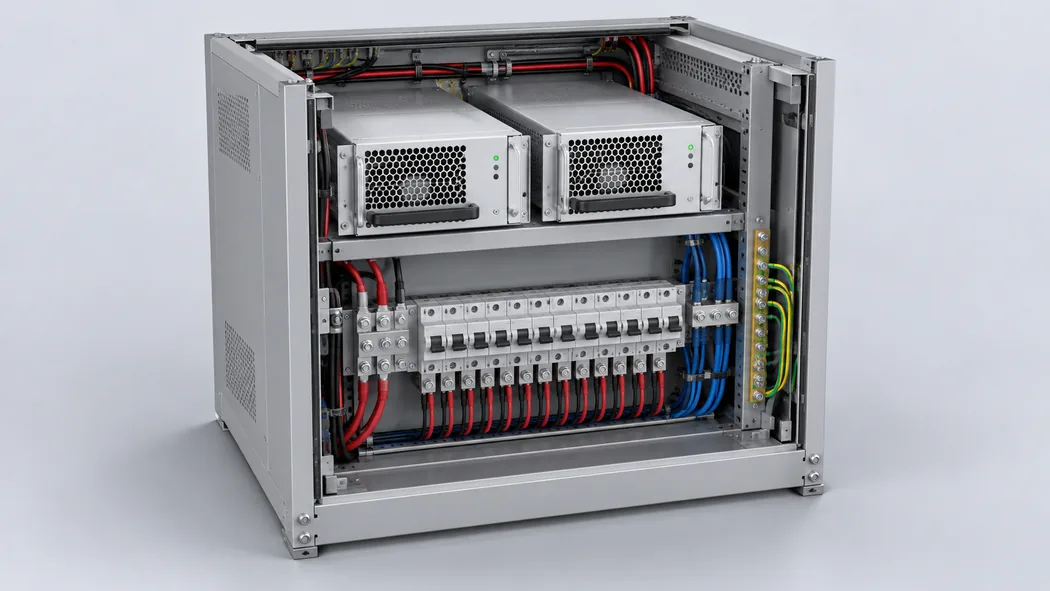
At the 50 A scale, branch organization can matter as much as total power. Several smaller converters can present a combined load inside 2700 W while one branch connector or copper path carries more current than intended. Conversely, a busbar rated for the aggregate current says nothing about each protection device or terminal. A distribution drawing should show the positive and return paths, branch ratings, and locations where voltage will be measured under load. Those details turn a catalog power figure into a meaningful electrical design.
What 2700 W means for continuous and redundant loads
A 2700 W output rating is a ceiling under conditions specified by the manufacturer; actual system load should be expressed at the module output. If downstream converters deliver 2400 W to equipment while converting at an illustrative 92% efficiency, their input demand is about 2609 W. The assumed efficiency is an example, not a GW-PA2700I or converter specification. It leaves little theoretical space beneath 2700 W for auxiliary branches or transients. A design using real converter curves, measured duty cycles, and the manufacturer’s operating envelope may reach a different result.
For a shelf with two modules, adding the nameplates gives 5400 W only as a combined nominal figure. If the shelf is intended to keep its load running after one module is removed or fails, surviving nominal capacity is one module’s 2700 W, subject to its actual derating and sharing behavior. A 3 kW continuous cabinet load might operate with both present in a capacity-combining arrangement; it would not be supported by one 2700 W module after a loss. That difference should be specified at the load and failure-state level, rather than hidden behind the phrase “dual power supplies.”
Whether two GW-PA2700I units can operate in parallel, and how they share current, cannot be confirmed from the public listing. A shelf could use active sharing, droop behavior, output isolation, or another arrangement, but those possibilities are not evidence of this model’s implementation. The backplane also has to handle removal and re-insertion without exposing the load to an unacceptable bus excursion. A module labeled Hot Swap is a candidate for a compatible serviceable shelf; the completed shelf defines the actual continuity behavior.
Locating the two published input windows
The 90–290 Vac range and 192–288 Vdc range describe two permitted voltage regions in Great Wall’s listing. The DC region is a high-voltage input. It is not a direct connection specification for a nominal 48 V battery plant. If a site has only low-voltage battery distribution, an upstream conversion stage or another PSU model would be required. A cabinet already fed by high-voltage DC may be a candidate if its complete voltage profile stays within the published window and the manufacturer approves its wiring and protection scheme.
The input-voltage range does not prove that 2700 W is available at the lowest AC or DC voltage, that both source types connect simultaneously, or that the module transfers between them. Input current rises as input voltage falls for a fixed output power, apart from conversion losses and power-factor effects. That can affect cable, connector, protective-device, and thermal design near low line. Request a voltage-versus-output-power or derating curve before using the maximum rating in a low-line facility design.
Hot-swap service depends on the shelf
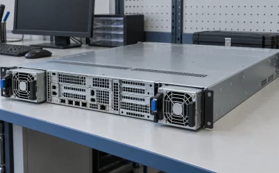
Hot-swap capability is useful only when the host was designed for the specific module. The shelf must guide insertion, mate the proper contacts in the intended order, manage inrush and output connection, and maintain load power from another source during removal if uninterrupted service is the goal. The module’s handle and chassis shape are visible hardware features, but they do not disclose the necessary electrical sequence. An unverified backplane should not be energized simply because the module appears to slide into it.
For replacement purchasing, identify the old unit from its complete label, not just its wattage and output voltage. Compare exact part number, revision, connector location, latch geometry, airflow direction, and control interface against the host-approved bill of materials. Public specifications do not establish any of those GW-PA2700I details. An adjacent Great Wall product can share an output category while differing at the mating plane or in its management signals. Photographs are poor substitutes for a controlled interface drawing.
For a new shelf, obtain the module drawing before reserving insertion clearance, ventilation space, rear access, and board area for the connector. Protection and fault isolation should prevent a failed module from disabling the common bus. If service with one module absent is required, the remaining source path must carry the expected load under actual operating conditions.
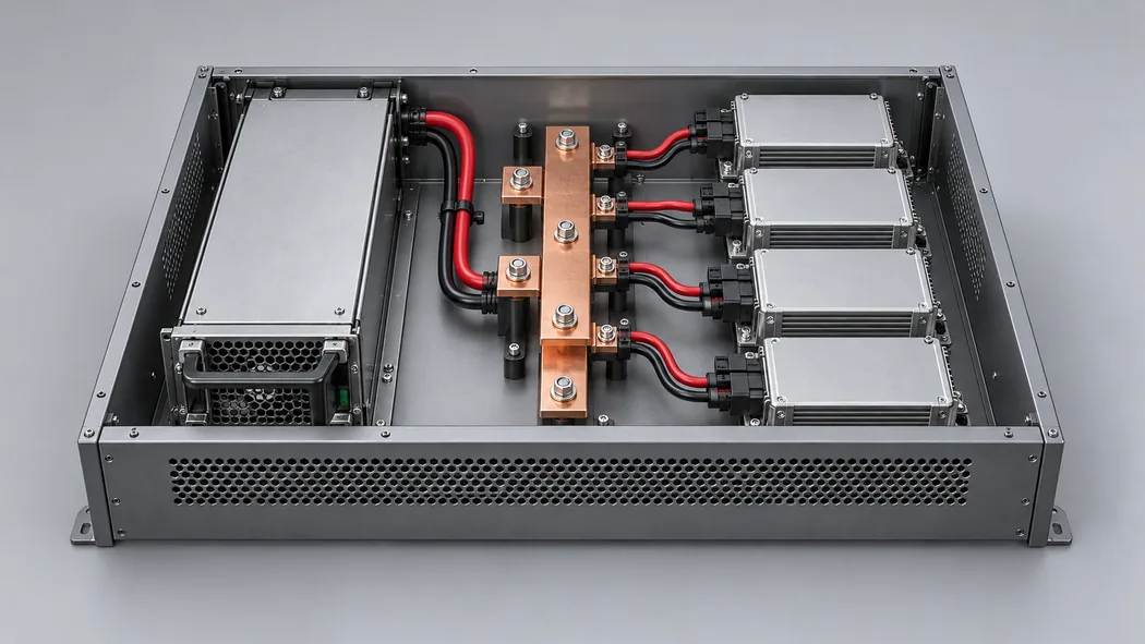
Airflow can become a constraint in a dense cabinet. A 2700 W conversion stage rejects some input energy as heat, and the surrounding shelf must provide the cooling conditions assumed by its rating. The public listing does not supply an efficiency figure, airflow direction, fan curve, or ambient-temperature derating for this model, so an exact heat load cannot be claimed. Placing a module near blocked vents or recirculated exhaust could reduce available capacity even though the electrical source and load seem well matched.
Reading GW-PA2700I against nearby 54 V choices
The useful comparison with GW-PAH3000I-F is not simply 2700 W versus 3000 W. GW-PA2700I is the 54 V, 2700 W listing with a 192–288 Vdc input range; GW-PAH3000I-F is listed at 53.5 V, 3000 W, and 188–400 Vdc. If an installation already has a regulated 54 V receiving bus and an input source inside the former range, GW-PA2700I may be worth investigating. If a facility’s high-voltage DC system extends outside 192–288 Vdc, the wider listed range of the neighboring model may be relevant, provided all its other interfaces match. Neither model can be chosen by these headline figures alone.
A 12 V CRPS server module addresses a different distribution architecture. Even a 2700 W 12 V unit would imply far higher output current than a 54 V unit of the same power, and its downstream converters and backplane would be arranged differently. A direct substitution between the two output-voltage classes would be unsafe for receiving electronics. Likewise, output power does not establish whether the 54 V module belongs in a particular server chassis, telecom shelf, or industrial cabinet. The physical interface and system wiring remain decisive.
Where only an exact spare is needed, the strongest documentation is the host manufacturer’s approved replacement list and the old module’s complete identifier. Where a new power shelf is being designed, the strongest early evidence is the GW-PA2700I technical datasheet and interface drawing. The public record is enough to identify a 2700 W, 54 V Hot Swap candidate and the two broad input regions. It is not enough to approve a connector, operating-current limit, load-step response, or live replacement sequence.
The boundary of a defensible 54 V application
GW-PA2700I can be considered for a serviceable 54 V power system whose source falls within the published AC or high-voltage DC range and whose output demand is compatible with the documented 2700 W operating envelope. At full listed power, the derived output-current scale is 50 A; that scale makes contacts, return paths, branch allocation, and load-terminal voltage part of the product decision. If continuity is required, the shelf must preserve capacity after a module loss rather than merely contain multiple nameplates.
The remaining unknowns have specific owners. Great Wall’s detailed documentation must resolve output tolerance, derating, mechanical dimensions, connector assignment, cooling conditions, and hot-swap behavior. The host designer must resolve distribution losses, branch protection, cooling path, and failure-state load. The site designer must resolve the actual AC or DC source profile. Keeping those boundaries explicit allows the 54 V and 2700 W catalog facts to guide sourcing without turning them into unsupported claims of drop-in compatibility or universal full-power operation.