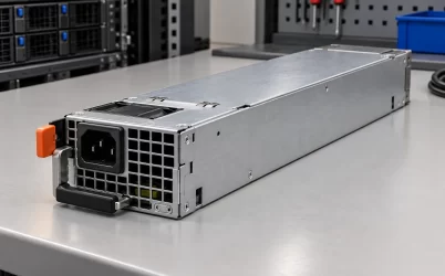
G1179-0550WNA is listed in the Powernexu catalog as a 550 W 2U power distribution board (PDB) assembly. Its multi-rail power budget depends on the combined output limits, standby demand, and capacity available after a PSU failure. Gospower describes the G1179 family as a 2U 1+1 PDB platform for use with 185 mm CRPS power supplies and standard ATX or customized outputs. For a specific host, the ordered board revision, module pair, and harness must support the required rail loads and operating states.
G1179-0550WNA catalog data and the G1179 platform
The official Gospower G1179 page describes the family architecture and output options. Its provision for 185 mm CRPS modules identifies the intended module format; electrical compatibility still depends on the selected PSU and board configuration. The public family description does not provide a G1179-0550WNA-specific load table or an approved PSU pairing.
The Powernexu G1179-0550WNA product page lists 550 W and output entries of +12 V at 45 A, +5 V at 25 A, +3.3 V at 25 A, −12 V at 0.5 A, and +5 V standby at 3 A. These catalog entries identify the rails to investigate, but they do not define a simultaneous-load envelope. Use the manufacturer’s exact-configuration load table to establish permitted combinations before assigning loads to the host.
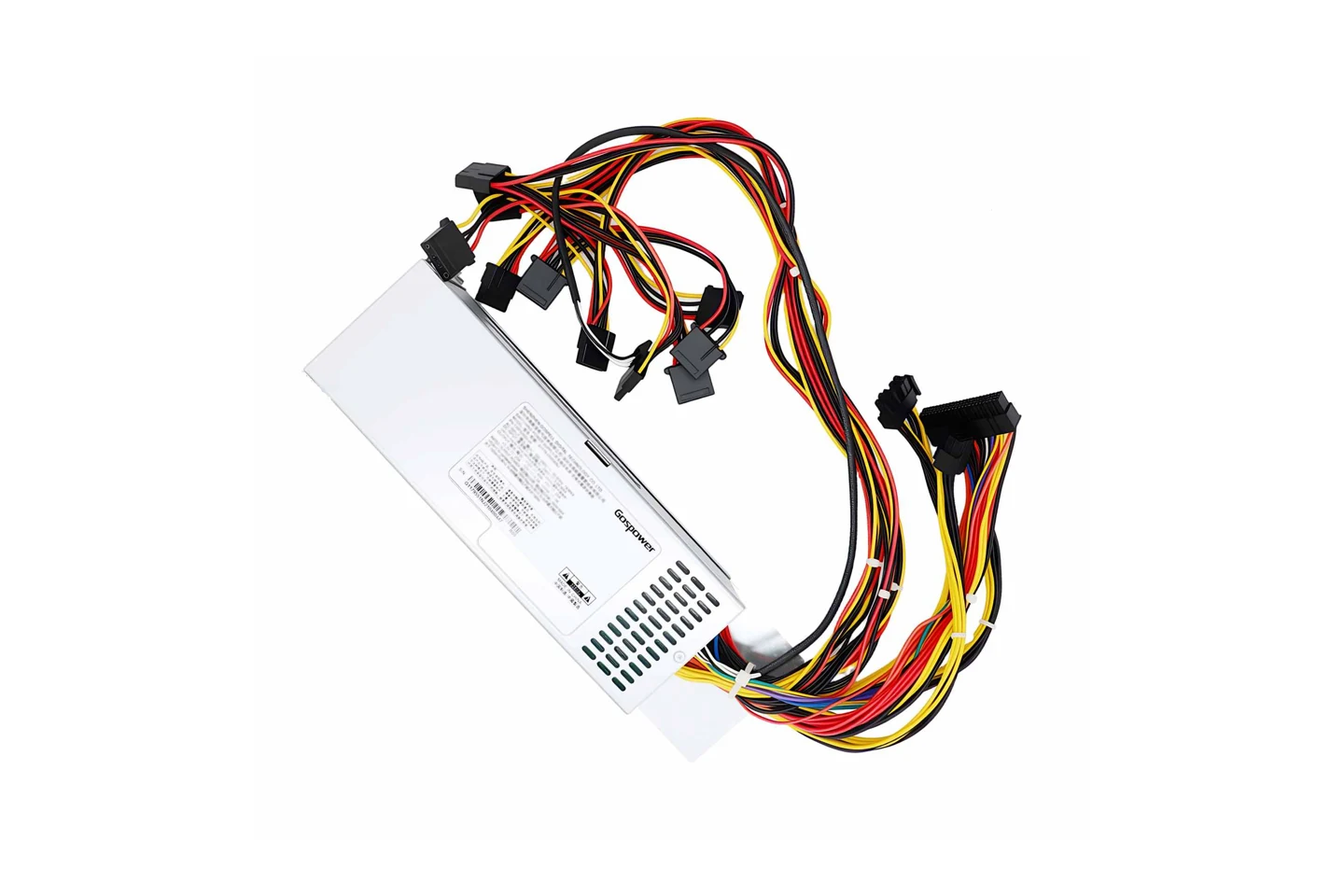
Separate the CRPS source input from the PDB interface
The catalog’s 90–264 V input entry must be matched to the component it describes. It is not a pin-level input specification for the PDB’s module-mating connector.
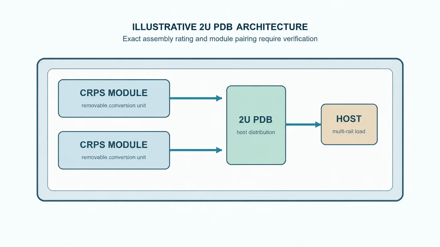
In a CRPS/PDB arrangement, the supply module’s external source input and the module-to-PDB interface are separate electrical boundaries. A catalog AC range may describe a supply module or a complete assembly rather than the distribution board itself. The exact configuration must identify the conversion stage, the module output presented to the board, and any auxiliary or standby supplies crossing that interface.
A system block diagram and the electrical specifications for both the approved modules and the PDB should define input types, operating ranges, connector assignments, polarity, and sequencing at each boundary. The CRPS module performs source-to-DC conversion, while the PDB provides the host distribution interface; any additional conversion or standby generation depends on the actual design. Connect mains only to the designated input of an appropriately rated supply module, never to an unidentified PDB connection.
Build the combined-rail and standby power budget
A headline wattage and individual rail entries do not define a simultaneous operating envelope. The output-load table for the exact board revision, harness, and module configuration should state which rail combinations are permitted, any shared power limits, and the conditions under which those limits apply.
The table should distinguish continuous loading from permitted transient loading and identify relevant input, temperature, and cooling conditions. It should also state whether the total output limit includes standby power, how auxiliary rails are generated or distributed, and whether connectors or harness branches impose lower limits than the rail-level specification.
Standby needs its own operating-state definition. Confirm its availability with the main outputs on and off, with either approved module absent, and during source loss or module transfer. Establish whether standby comes from the modules, conversion on the board, or another documented arrangement, and whether any sharing or combined-output restrictions apply.
Compare measured host demand with the combined-output and branch limits. The load record should cover each required rail and branch, continuous demand, peak magnitude and duration, startup, shutdown, and fault or maintenance states. Keep main-output demand and standby demand separate until the assembly documentation explains how both count toward the total.
For a rail-by-rail calculation, use P = Σ(|V| × I), with currents taken at the same operating state. As a hypothetical host example, 24 A at +12 V, 10 A at +5 V, 8 A at +3.3 V, 0.1 A at −12 V, and 1 A at +5 V standby total 288 + 50 + 26.4 + 1.2 + 5 = 370.6 W at the output rails. This is an illustrative load, not a tested G1179-0550WNA configuration. Being below 550 W would not by itself demonstrate suitability: the combined-load table, each branch limit, and surviving-module capacity must also accommodate it. Upstream module sizing must include applicable downstream conversion and distribution losses.
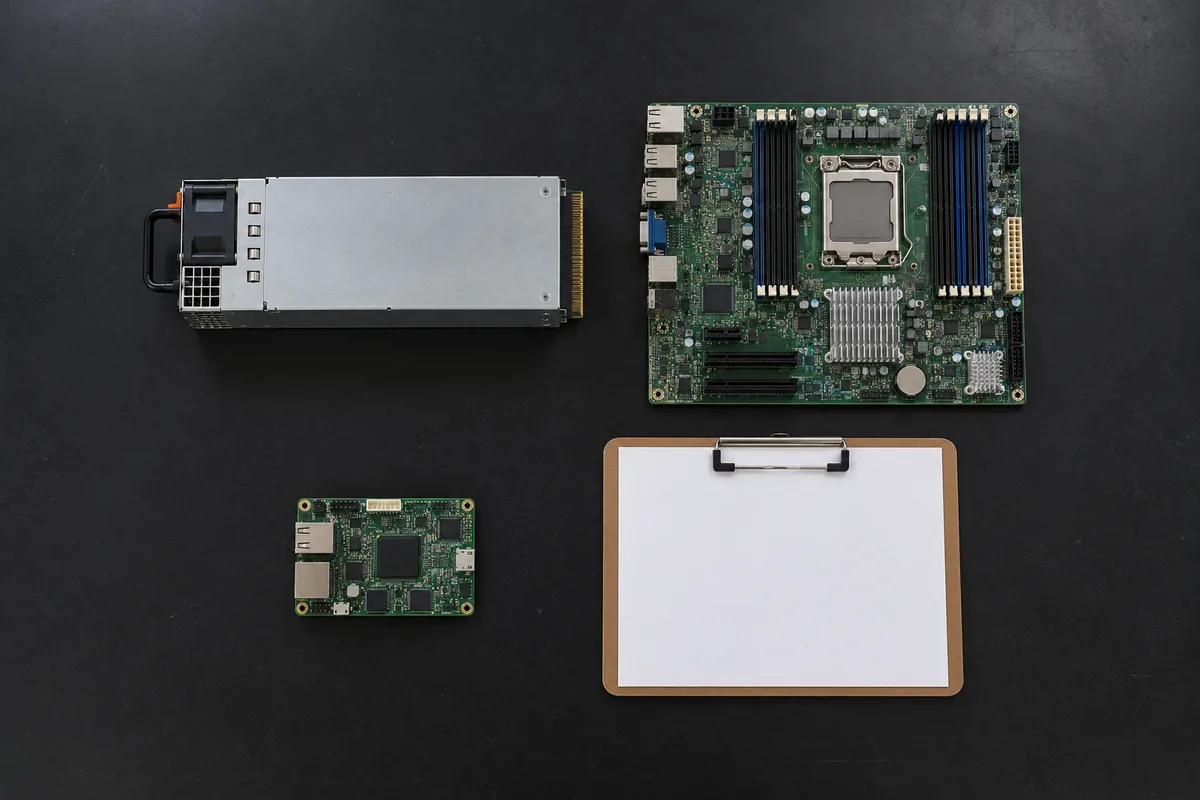
AI illustration: an unpowered server power module, motherboard, and management controller board represent the loads that may need a separate standby budget. This is a generic component view, not a drawing of the G1179-0550WNA circuitry.
Account for the surviving module in 1+1 operation
In the G1179 family’s 1+1 architecture, the protected load must remain supportable when one module is unavailable. The capacity available in that state depends on the approved module pair and the distribution configuration. Adding two module nameplates does not establish the protected load.
Request the exact approved PSU part numbers and hardware revisions, together with any pairing restrictions. The documentation must define each module’s available output under the intended source and environmental conditions, current-sharing behavior, and operation when either module or feed is lost.
For redundant operation, the permitted host load must remain within the documented surviving module capability and the board, rail, connector, and harness limits. The transition to one-module operation also matters: steady-state capacity alone does not establish acceptable voltage behavior during a loss or removal event.
Use the configuration-specific hot-swap and service procedure when planning live replacement. It should identify permitted operating states, insertion and removal requirements, status indications, and any required load reduction. Gospower describes PSU hot-swap support at family level; the service procedure must still match the selected module, board, and host arrangement.
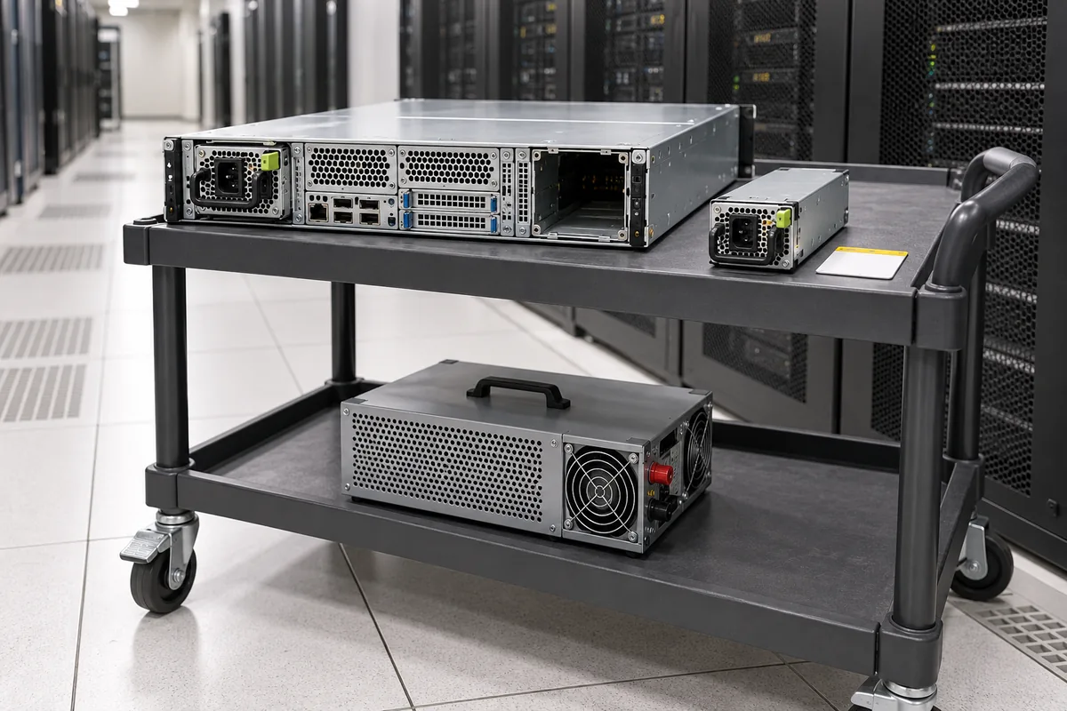
AI illustration: a complete server with one seated power module, an empty redundant bay, and a spare module shows the service-access problem during replacement. Before removing a module, establish that the remaining power path can support the protected load.
Match the power rails and control connections
The G1179 family’s provision for standard ATX or customized outputs makes exact connector documentation essential. Rail names, connector appearance, keying, and wire colors do not prove that a delivered assembly follows a particular ATX pinout. A family designation also does not establish that two suffixes or revisions use the same harness.
Obtain pin maps for the module-to-PDB interface and every host-side connector. Verify connector and mating-part numbers, populated contacts, voltage assignments, returns, contact ratings, wire specifications, and any branch protection. Compare the documented harness with the actual host wiring, including intermediate backplanes and adapters.
Control contacts require the same scrutiny as power contacts. Determine whether the exact configuration uses enable, power-good, remote-sense, presence, fault, or management connections. For each applicable signal, verify its direction, electrical levels, polarity, timing, and behavior during startup, shutdown, standby, and module loss. Do not infer those details from a generic ATX diagram.
Resolve undocumented or conflicting pin assignments before energizing the assembly. A mechanically mating connector is not evidence of electrical compatibility.
Fit the PDB, harness, and CRPS bays into the 2U chassis
“2U” describes the family’s form-factor context, not a complete installation envelope. Powernexu lists 265 × 77 × 84 mm for G1179-0550WNA. Confirm the measurement boundaries and mounting geometry against the drawing for the supplied revision before using those catalog dimensions for chassis design.
The controlled drawing should identify the part number and revision, measurement datums, overall envelope, mounting-hole locations, fastener requirements, and module-mating positions. It must show connector projections, brackets or housings included in the dimensions, required clearances, and the module insertion and extraction path.
Compare that drawing with the host chassis and installed harness. Check connector access, cable routing, permitted bend radii, and the specified airflow path. Photographs can help identify differences, but they cannot replace dimensions, tolerances, or a documented mounting interface.
Keep the load budget tied to the supplied assembly
For an existing system, identify the installed board revision, PSU part numbers, harness identifiers, and chassis, then attach a measured rail-by-rail load record. The corresponding configuration documents should cover:
- Identity and scope: confirmation of the G1179-0550WNA designation, orderable assembly part number, board revision, included modules and harnesses, and any customized outputs.
- Electrical ratings: an exact-configuration datasheet defining the 550 W operating envelope, its operating conditions, simultaneous rail-load limits, standby limits, transient allowances, and derating.
- Input boundaries: a block diagram and interface specification distinguishing the module source input from the PDB input, with connector assignments and permitted operating ranges.
- Approved module pairing: PSU part numbers and revisions, pairing restrictions, sharing behavior, surviving capacity, and hot-swap requirements.
- Host interface: connector and harness drawings, pin assignments, branch ratings, protection details, and applicable control-signal specifications.
- Mechanical definition: a revision-controlled assembly drawing with dimensions, tolerances, mounting details, mating positions, and service clearances.
- Verification evidence: applicable test reports or a manufacturer-approved qualification procedure covering the proposed load, standby states, source or module loss, and recovery behavior.
The assembly datasheet should connect the 550 W catalog designation to the delivered hardware and its operating conditions, especially the combined rail limits and one-module operating state.
A host can remain below its total power target while overloading an auxiliary rail or a harness branch. Keeping the rail budget tied to the ordered G1179-0550WNA assembly, its module pair, and its wiring gives the 550 W designation a useful engineering context.