An equipment order includes both the vision package and the powered handling accessory. Each option has been assessed separately, but their combined demand can exceed one output even when total power remains acceptable. For an OEM specifying a power supply for industrial equipment, the useful question is which combinations of options the electrical design can actually support. That requires a relationship between installed options, permitted operation, and the particular output restrictions each combination consumes.
The following hypothetical inspection instrument demonstrates how to find those interactions. Its requirements and candidate limits are fictional teaching inputs, not manufacturer specifications. The method produces an option capability map: combinations supported by the stated assumptions, combinations that exceed a named limit, and combinations still needing evidence. Basic input, installation, and environmental prerequisites remain part of the underlying industrial power supply selection assessment.
Separate an installed option from its electrical contribution
Assume the instrument contains a base controller and can accept a vision subsystem, a powered handling subsystem, or both. The vision head and handling accessory are separate physical assemblies. Their presence in one order establishes equipment population; the operating sequence establishes which demands coincide. Those are separate inputs to the capability map: installed accessories identify population, while their coincident operating demands determine loading.
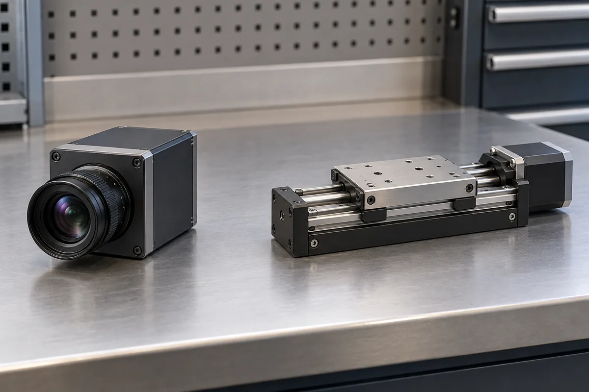
Begin with the base machine’s demand at the power assembly’s output terminals. Then describe each option’s additional contribution at that same boundary. If an accessory replaces an existing load, its contribution is the change between the two arrangements, rather than its entire consumption added on top of the removed load. Likewise, an option figure already included in a configuration-specific equipment total must not be added again.
For this exercise, the base requires 3 A at 24 V. Vision adds 2 A at 24 V and 3 A at 12 V. Handling adds 4 A at 24 V. Assume these demands can coincide continuously in a permitted operating state. They include the distribution allowances assigned to this example; no additional conversion loss is added afterward. Startup and temporary events require separate records where they differ.
Keep the contribution as a set of rail requirements. Calling vision an 84 W option is arithmetically correct at the assumed voltages, but hides how its demand divides between outputs. Handling contributes 96 W entirely at 24 V. Similar option wattages therefore place different demands on the same multi-output assembly.
Option descriptions also need an operating basis. A vision head’s acquisition mode can differ from its idle mode; a handling accessory may have distinct motion and holding states. Use documented requirements for actual equipment. This example deliberately treats the listed contributions as fixed continuous values so the combination logic remains visible without inventing device behavior.
The combined option fails at 24 V before total watts run out
Suppose fictional configuration A permits 8 A on its 24 V output, 10 A on its 12 V output, and 300 W combined continuous output under one stipulated installation condition. Assume these restrictions apply simultaneously as stated. Configuration A is an exercise label, not a commercial model or ordering code.
| Installed combination | 24 V demand | 12 V demand | Total DC demand | Comparison with fictional A |
|---|---|---|---|---|
| Base | 3 A | None | 72 W | Within the three stated limits |
| Base and vision | 5 A | 3 A | 156 W | Within the three stated limits |
| Base and handling | 7 A | None | 168 W | Within the three stated limits |
| Base, vision, and handling | 9 A | 3 A | 252 W | Exceeds the 24 V limit by 1 A |
The combined row requires 24 × 9 + 12 × 3 = 252 W. Its total is below 300 W, and its 12 V demand is below 10 A. Nevertheless, 9 A exceeds the assumed 24 V allowance of 8 A. Spare capability elsewhere does not establish permission to transfer it to the restricted output.
The remaining capacity is therefore more informative as several allowances than as one wattage figure. After the base load, A has 5 A remaining at 24 V, 10 A at 12 V, and 228 W under its combined limit. Vision fits those allowances independently. Handling also fits them independently. Together, their additional 6 A at 24 V exceeds the remaining 5 A.
This exposes an option interaction: approval of each addition against the base machine does not establish approval of their combination. The offending pair is useful information. If a later option uses only another supported output, excluding it simply because the vision-and-handling pair fails would misidentify the restriction.
Preserve any manufacturer-defined grouped limit alongside individual and total limits in a real assessment. An acceptable total cannot override a grouped restriction either. Where official documents conflict about a material limit, examine revisions and conditions; if the conflict remains, leave the affected combination unresolved. Choosing the more convenient value would manufacture a capability that the evidence has not established.
Map allowed combinations without inventing a maximum machine
The four-row example is small enough to inspect directly. A machine with many options can create substantially more combinations, including combinations the commercial design does not permit. Build the map from offered equipment and accepted operating rules. A theoretical machine containing every catalog option is irrelevant if mechanical or functional restrictions prevent its construction.
Record a mutually exclusive pair as an installation restriction. For example, two accessories might occupy the same station. Their joint row can then be excluded because the equipment cannot contain both. This differs from two installed accessories whose demanding operating states are kept apart by the machine sequence. The latter equipment still needs a combined-population row with its permitted states attached.
Distinguish a local overload from an unresolved interaction. The hypothetical combined row exceeds a stated arithmetic boundary. A real row whose output population rules are missing has a different status: its support is unestablished. Both prevent an unrestricted promise, but the remedies differ. One needs a changed electrical arrangement or requirement; the other may first need manufacturer clarification.
Checking pairs alone can miss a larger combination. Several small options may each fit the base and every individual pair while collectively exceeding a shared restriction. Under fixed nonnegative demand assumptions, adding options cannot reduce the calculated total. That can simplify screening, but replacing loads, changing operating modes, or altering cooling invalidates a simple additive interpretation.
A useful capability entry names the reason for exclusion precisely: combined vision and handling exceed the assumed 24 V continuous allowance. It should not say merely that the premium machine needs more power. The specific statement tells electrical engineering which output must change and tells product planning which option relationship created the issue.
Uncertainty should remain visible at option level. If handling demand is not yet established for the required duty, assigning it zero current would make every containing row appear easier. Mark those rows unresolved instead. The map can still retain supported findings for other combinations without allowing a missing contribution to become an implicit allowance.
Output modules and option wiring add local boundaries
Configurable supplies are an established commercial category. Advanced Energy’s industrial configurable power supply overview describes equipment containing subsystems with different DC requirements. Its category description supports investigating that architecture; it does not establish module population, output allocation, or allowable combinations for a particular assembly.
For a proposed modular implementation, connect the option map to the actual output modules and their supported relationships. A higher-capacity front end would not resolve the example’s 24 V shortfall if the restricted output module remained unchanged. A different output arrangement must address that restriction while respecting any grouped and total constraints accompanying the change.
A module that can supply the required current individually does not prove that it can operate in the proposed chassis population. Applicable documentation must establish the permitted modules, positions, cooling conditions, and shared restrictions. Similarly, omitting an unused output module changes the proposed population. The manufacturer’s rules determine whether that population is supported and which accessories it requires.
A configured power assembly can include external harnesses that change with the option population. For the capability map, the important question is where option currents join. Separate accessory branches can meet at one connector, common return, or distribution segment. Each branch may remain within its local allowance while their combined current exceeds the shared segment’s documented capability.
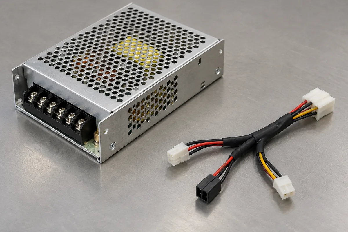
Suppose vision and handling use distinct connectors but obtain 24 V through one upstream connection. Their separate connector ratings cannot establish the allowance of that common connection. Trace the coincident current through each shared element. No connector rating, wire size, or acceptable temperature rise can be assigned from this hypothetical example; actual component and assembly evidence must supply those limits.
This gives two different explanations for an unsuccessful combination. The source output may be insufficient, as in fictional A, or downstream distribution may impose an earlier restriction. Increasing source capacity addresses the first explanation. It does not by itself increase a harness, terminal, or PCB path’s allowable current. Locate the limiting element before specifying the change.
Restricting concurrency changes what the option package can do
Return to the instrument containing both accessories. Prohibiting their demanding states from overlapping could reduce simultaneous 24 V demand, but that creates a different operating promise. It is useful only if the equipment can perform its required work within the restriction. An operator preference to avoid overlap does not establish that the machine prevents it.
Describe the proposed restriction at the functional level before crediting any current reduction. Can the handling stage remain inactive during image acquisition? Does vision retain its full listed demand while waiting? Is the controller required to support another operation during that interval? The fixed contributions in the original exercise do not answer these questions, so they cannot establish a reduced combined demand.
The revised requirement needs the accessory demands for the newly permitted states. Do not subtract the entire vision contribution merely because image capture stops; the head may still require operating power. Nor should absence of motion imply zero handling current. Actual subsystem documentation and the equipment sequence determine the contribution left during each state.
Scheduling also carries a production consequence. Separating operations that previously overlapped can extend cycle time, change the handling sequence, or reduce the usefulness of the combined package. Those consequences belong beside the electrical benefit. A cheaper supply arrangement has not preserved the original equipment offer if it achieves capacity by removing required concurrent functionality.
If both options must sustain the original simultaneous demand, retain the 9 A requirement at 24 V and 3 A at 12 V. Investigate a documented arrangement covering that allocation and its distribution paths. If accepted operating restrictions genuinely reduce the demand, assess the revised states instead. Neither route follows automatically from the combined 252 W figure.
The capability map then expresses a specific commercial boundary: which accessory combinations can perform which operations under the stated power arrangement. For this fictional instrument, unrestricted combined operation exceeds A’s assumed 24 V limit even though the other stated limits remain satisfied. That finding belongs with the combined option’s functional description, so adding the accessory pair does not silently promise an operating state the electrical design cannot support.