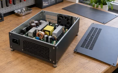
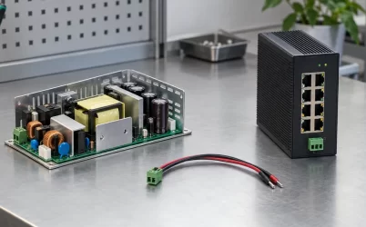
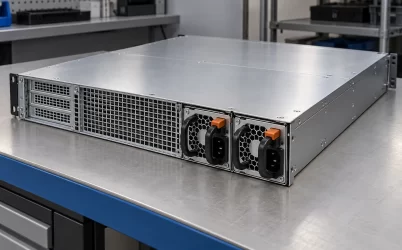
An isolated industrial AC-DC power supply separates its input and output through an insulation barrier. That description does not promise that a switching disturbance cannot cross the boundary. A transformer can lack an intended conductive connection between windings while still having capacitance between them. When voltage changes rapidly, that capacitance provides a path for displacement current. The practical question is therefore more specific than whether the supply is isolated: where does the high-frequency current return, and which part of the installed equipment experiences its effects?
This distinction matters when an isolated supply powers a controller that also connects to a grounded machine, a communication cable, or test equipment. A satisfactory insulation specification and a troublesome noise observation can coexist. One describes an insulation requirement under stated conditions; the other concerns a complete operating circuit. Neither observation, by itself, establishes the other.
The barrier answers one question, not every frequency question
A useful first drawing separates the primary power circuit, the secondary power circuit, the equipment chassis, and the external connections. The transformer transfers energy between the power circuits without making their winding conductors one continuous wire. However, nearby conductive surfaces also form capacitances. Their presence does not require an intentional component bridging the isolation barrier.
Analog Devices describes this mechanism in its discussion of EMI paths in switching power supplies: transformer parasitic capacitance can carry high-frequency current between primary and secondary circuits. Its offline-supply example also identifies capacitive coupling from a switching device to a heatsink. These are particular paths to investigate, rather than evidence that every supply has the same noise behavior.
The consequence is a distinction between conductive continuity and frequency-dependent coupling. An open circuit on a continuity check does not characterize the impedance of every parasitic path at switching frequencies. Conversely, finding a high-frequency disturbance across two circuit regions does not establish that their insulation has failed. The mechanism must be identified before the observation becomes a diagnosis.
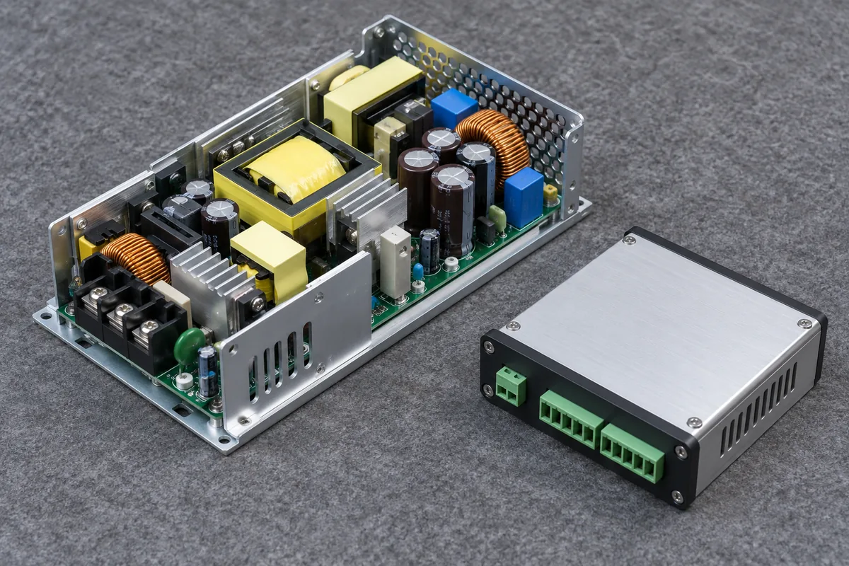
A complete converter assembly can contain switching, magnetic, control, and output regions. The enclosure does not reveal which internal surfaces couple most strongly or where a particular insulation boundary lies. A photograph can identify the physical assembly under discussion, but it cannot establish barrier capacitance, an isolation rating, or the route taken by an observed current.
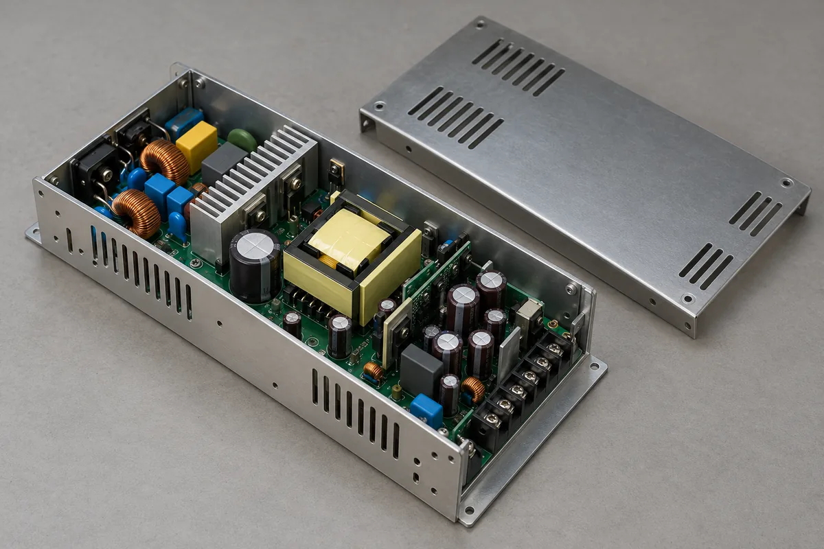
This is also why a withstand-test number cannot substitute for an EMI model. A specified voltage test concerns a particular insulation evaluation. It does not supply the capacitance, voltage waveform, or installed return impedance needed to predict high-frequency coupling. Any claim about permissible continuous working voltage must come from the applicable manufacturer’s documentation, separately from this noise analysis.
A changing voltage needs a complete current loop
The familiar capacitive relationship, current equals capacitance multiplied by the rate of voltage change, explains why a small capacitance can matter during a fast edge. Texas Instruments uses this relationship in its isolated-bias transformer discussion, where interwinding capacitance and switching transitions produce common-mode current pulses. That example concerns an isolated bias circuit; it is not a specification for an unidentified industrial mains supply.
Consider a deliberately hypothetical calculation. A capacitance of 10 picofarads subjected to a voltage slope of 20 volts per nanosecond gives an instantaneous current of 0.2 amperes during that slope. These assumed values illustrate sensitivity to an edge. They are not measured parameters of a product, and the result is not an RMS current, a touch-current result, or a continuous current capability.
The arithmetic alone is incomplete because it says little about the rest of the loop. Current entering a secondary region needs a return route. That route can involve other capacitances, connected equipment, chassis structures, or intentional components in the documented design. Its impedance helps determine the voltages that appear at particular locations. Identical transformer capacitance does not guarantee identical installed behavior when those connections differ.
For example, imagine the same controller first operating without an external data cable and then connected to another grounded assembly. The added connection may change the available high-frequency return network. It does not automatically make the installation better or worse. A different receiver reference or a different loop geometry can change the observed disturbance even though the supply module and its insulation barrier are unchanged.
That reasoning points toward a concrete investigation: identify both ends of the coupling path and the route back to its source. A label such as “secondary noise” locates an observation but leaves the circuit unfinished. The source of the edge, the coupling element, the return network, and the affected interface are separate pieces of evidence.
Output ripple and movement relative to the chassis are different observations
A controller normally uses the voltage between its positive and return conductors. A measurement between either conductor and chassis answers another question. If both conductors move together relative to a third reference, their movement need not appear with the same magnitude in the voltage between them. Real equipment can convert part of that disturbance into a differential error through unequal impedances, but the amount cannot be assumed.
This gives an important reading rule for test results. A small differential ripple measurement does not establish small common-mode disturbance at every external interface. Equally, a visible terminal-to-chassis waveform does not directly show that the controller’s supply voltage exceeded its permitted differential range. Record which two points defined each voltage before comparing traces or assigning a cause.
A supply does not remain electrically alone after installation. A separate controller introduces its own reference conductors and interfaces, while the machine may contribute chassis connections elsewhere. Physical separation between the assemblies helps explain the system boundary; it does not prove that their references float independently or that a particular connection is permitted.
A useful example is a controller that communicates correctly on an isolated bench but reports errors after installation. Barrier capacitance is one possible contributor, not a verdict. The changed installation may also alter cable routing, receiver reference, grounding, or an unrelated disturbance source. The useful question is which changed path explains the specific error and whether controlled evidence supports that explanation.
Related cabinet wiring and common-mode return paths belong in that investigation because the installed conductors complete the environment around the supply. The insulation barrier remains important, but it cannot describe the entire cabinet’s interference behavior on its own.
Observe the installed path without silently replacing it
The measurement arrangement belongs on the circuit drawing. An instrument connection can add a reference, capacitance, or another return route. That does not make measurement impossible; it means the observed configuration must be described accurately. A waveform taken with one instrument arrangement should not automatically be treated as the waveform that existed before the instrument was connected.
Start by defining the receiver and the symptom. An analog reading error, a communication failure, and a conducted-emissions result are different outcomes. Evidence for one does not automatically quantify another. Place the observation boundary around the actual outcome, then ask which electrical quantities are needed to connect that outcome to the suspected path.
A controlled comparison should preserve the conditions that matter to the claim. If a cable is disconnected to investigate a return route, document that change and its consequence. An improvement in the modified arrangement supports a relationship worth examining; it does not validate the original arrangement or prove that the cable itself was defective.
Timing can strengthen or weaken the explanation. A disturbance consistently associated with a switching event is more informative than an isolated screenshot with no operating context. Still, correlation alone cannot distinguish every coupled path. Another transition can occur at the same time, and the receiver can respond after its own delay. Keep the mechanism as a hypothesis until the observations discriminate between plausible alternatives.
All such work must preserve the applicable safety boundaries and use equipment suitable for the voltages and references involved. This article does not prescribe a probe connection, a chassis bond, or access to an energized primary circuit. Those choices require the actual equipment documentation and the qualified test plan; an explanatory equivalent circuit is not a connection instruction.
Operating state also matters to the explanation. A comparison made at one load and one input condition establishes behavior there. If the converter changes its switching behavior elsewhere in its documented range, the excitation of the parasitic network may change as well. This is a reason to record state, not a prediction that a specific model will become noisy at light load or at a particular line voltage.
The receiver can change state too. An interface that is inactive during a quiet observation may become relevant when communication starts, and a machine connection may appear only during a particular process step. A credible system explanation identifies when the complete path exists. Otherwise, a test can faithfully capture a benign state while leaving the reported operating event unexamined.
These distinctions help separate two kinds of acceptance evidence. The supply’s documentation can establish its stated insulation and operating conditions. A system evaluation can establish the behavior of the assembled equipment under the tested conditions. Neither record should be rewritten to make it stand in for the other. Keeping both scopes explicit makes a later change of controller, cable, or supply easier to assess.
For an equipment revision, retain a short boundary record: which circuit regions were separated, which external connections were present, where the receiver reference was defined, and what observation supported the conclusion. This is more reusable than a photograph of a satisfactory trace alone. It allows the next engineer to recognize when a changed connection has altered the question that the earlier result answered.
Change the mechanism you have evidence for
Once the path is understood, the design question becomes narrower. Is the dominant issue the edge exciting the path, the coupling between regions, the return network, or the receiver’s sensitivity? These categories suggest different investigations. They do not authorize changing an insulation construction or removing a component that serves a safety or functional purpose.
Reducing one capacitance can reduce current through that particular path under otherwise comparable conditions. It does not prove that every measured emission will improve. Current can redistribute through other paths, and the receiver may be sensitive to a different part of the spectrum. Likewise, a slower edge may alter the excitation while introducing other design consequences that require evaluation.
A supply comparison therefore needs consistent observation boundaries. Comparing one unit’s differential output ripple with another unit’s terminal-to-chassis waveform is not a comparison of the same behavior. Nor does a higher isolation withstand rating, by itself, establish lower common-mode coupling. Ask for evidence addressing the actual interface and operating conditions instead of using an unrelated specification as a substitute.
There is a useful limit to what can be inferred from a successful change. If rerouting a documented cable removes an error, that result applies to the tested configuration. It does not establish immunity across every cable length, load state, machine arrangement, or supply variant. Expanding the claim requires expanding the supporting evaluation, rather than relabeling a single improvement as a universal cure.
The final engineering record should connect the original symptom, the proposed loop, the controlled change, and the resulting observation. Keep the insulation evidence alongside it as a separate requirement. An isolated industrial AC-DC power supply can satisfy its specified insulation conditions while participating in a high-frequency current loop; understanding that loop is what turns a broad isolation label into a useful system explanation.