A 2200W 24V enclosed power supply needs documented reverse-power capability only if the test station expects it to absorb energy from the DC device. Its forward wattage does not establish that capability. For battery or load-emulator testing, specify reverse current, power, duration, and energy destination separately. If that destination depends on AC, the station also needs a defined response when AC becomes unavailable.
This distinction changes the purchase before enclosure dimensions or control options become decisive. A source-only station, a station with a separate electronic load, and a regenerative station can all involve nominally 24 V equipment near this power class. They perform different jobs. Begin with the intended test cycle and its interrupted state, then determine which assembly must source energy, which must absorb it, and what remains available after a fault.
Start with the test cycle’s current direction
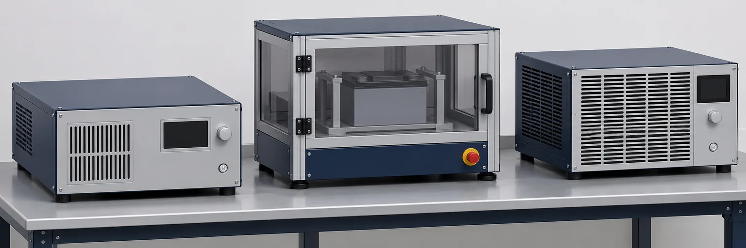
A battery test fixture can contain a power source and a separate load in physically distinct housings. During charging, energy travels toward the battery. During discharge, the battery supplies energy to another destination. The same two DC terminals may participate in both intervals, but that does not make every connected power supply a controlled sink. The station architecture must assign the discharge function explicitly.
Use a clear sign convention in the test specification. For this discussion, positive current means current delivered from the station’s source toward the device under test. Negative current means current returned by that device toward the station. Voltage and current measured at the same DC boundary then identify the direction of power. Record the convention beside the waveform; a negative number without a defined measurement direction is ambiguous.
A load emulator also needs this examination. Depending on its documented design and programmed behavior, it may only consume power or may actively return power to the connected bus. Its product name alone does not resolve the question. Ask whether any normal command, transition, reset, or fault can drive current into the source terminals. Include conditions in which the emulator remains powered while the source is disabled.
There is an important difference between tolerating externally applied voltage and regulating reverse current. A supply may have a specified limit for backfeed exposure without offering a usable discharge function. Conversely, an actively controlled sink needs an operating envelope, control method, and destination for absorbed energy. Neither capability should be inferred from voltage adjustment, current limiting, or a remote on/off input.
If the planned test never returns energy to the source, bidirectional conversion may add no useful function. A separate discharge load can keep the source’s job limited to forward operation, provided the switching and isolation arrangement prevents unauthorized reverse exposure. If the cycle repeatedly changes direction through one interface, a documented source-and-sink assembly may simplify that task. The appropriate choice follows the electrical boundary, not the shared wattage label.
Four separate permissions belong in the purchase specification
The forward rating answers how much DC power the supply can deliver under stated conditions. Reverse operation introduces three more questions: what reverse input the equipment permits, where the energy goes, and whether that destination remains available throughout the required event. Keeping these permissions separate prevents a supplier’s confirmation of one capability from being mistaken for confirmation of all four.
| Specification boundary | Information needed | What it does not establish |
|---|---|---|
| Forward output | Voltage, current, power, and applicable operating conditions | Permission to absorb current |
| Reverse operation | Permitted voltage, current, power, duration, and control behavior | An available energy destination |
| Energy destination | Dissipation, storage, or conversion back to an acceptable AC system | Continued operation after that destination is lost |
| Interrupted operation | Residual energy handling and defined abort behavior | Completion of the normal test cycle |
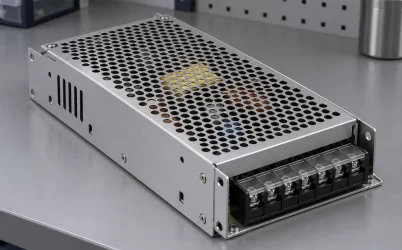
Great Wall’s July 8, 2025 GSP2200W series datasheet provides a useful forward-output example. It lists GW-GSP2200W-24 at 24 V, 92 A, and 2,200 W. Unless otherwise specified, its parameters use 230 V AC input, rated load, and 25°C ambient conditions. Those entries establish documented source ratings; they do not, by themselves, establish a reverse-current operating envelope.
The printed voltage and current multiply to 2,208 W, while the document states 2,200 W. That difference is not additional usable capacity. Retain the stated power ceiling and obtain clarification if the design depends on simultaneous operation at the printed current and voltage limits. Applicable input and temperature derating also remain part of the forward specification.
Powernexu’s GW-GSP2200W-24 product entry identifies that commercial model. Its suitability for a station that returns energy requires additional, explicit evidence about the proposed reverse exposure or an architecture that keeps that exposure away from the supply. An omitted reverse specification supports neither a claim of reverse capability nor a definitive claim that reverse current is prohibited.
Manufacturer documentation for regenerative converters illustrates why separate directional specifications matter: DC-to-AC conversion has its own operating conditions and protection behavior. A forward power-class label cannot substitute for those details. Procurement should request the exact ordered configuration’s reverse limits rather than transferring figures from another direction, variant, or family member.
A short return interval can dominate the sink requirement
Consider a hypothetical 24 V load-emulator cycle with a five-second interval drawing 60 A from the station, followed by a two-second interval returning 40 A. The complete cycle repeats every 30 seconds. These are invented design inputs for explanation, not measurements or approved operating points for any named supply. Assume the terminal voltage remains at 24 V during both intervals.
The forward interval requires 24 V × 60 A, or 1,440 W. The returning interval presents 24 V × 40 A, or 960 W, to the absorbing path. Over two seconds, that path receives 960 W × 2 s = 1,920 J. A source comfortably sized for the forward interval can therefore still be unsuitable for the station if no assembly is authorized to accept the returning current.
For a dissipative sink, the returned energy averaged over the entire 30-second cycle is 1,920 J ÷ 30 s = 64 W. That average helps frame repeated thermal loading, but it does not reduce the required 960 W absorption during the return interval. Pulse power, pulse energy, repetition, cooling, and allowable temperature must all fit the load manufacturer’s limits. A 64 W continuous rating alone would not demonstrate suitability.
For a regenerative path, the same 1,920 J is DC energy presented to the converter, not a promise that all of it reaches the AC system. Conversion losses and auxiliary consumption affect the balance. More importantly, the converter must support the actual DC voltage and reverse current throughout that interval. A battery whose voltage changes during discharge requires evaluation across that changing voltage, not just at its nominal label.
The hypothetical fixed-voltage calculation is deliberately narrow. For a real cycle, determine returned energy by integrating reverse power over time, using voltage and current at the defined interface. Include transition events rather than averaging them away. If the station can interrupt the cycle halfway through a return interval, the remaining energy after that interruption becomes a separate requirement for the abort design.
This separates three purchasing numbers that are often confused: maximum reverse current, maximum reverse power, and energy per event. Two stations with the same reverse peak may need very different sinks if one returns energy briefly and the other discharges a battery for minutes. The duration and repetition belong beside the peak, not in a later installation note.
What happens when the AC destination disappears?
A regenerative energy path ends at an available AC system, not inside the converter. In a documented grid-return architecture, the converter takes DC energy from the test device and transfers it to AC under specified voltage and frequency conditions. A separate dissipative path instead converts the returned energy into heat. These are alternative destinations, and their availability can change independently.
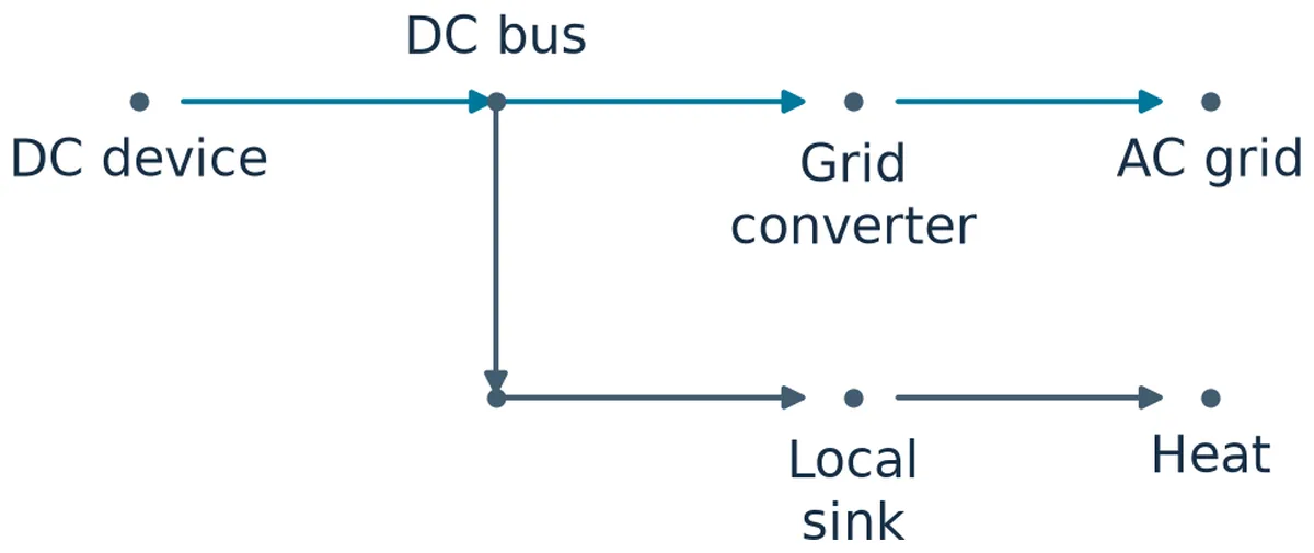
Loss of AC therefore changes more than the station’s ability to draw input power. It can remove the destination used during discharge while the battery or active emulator remains capable of supplying DC energy. Manufacturer documentation for grid-return equipment includes AC-fail and anti-islanding protection. Such protection addresses converter behavior; it does not establish that the test device immediately stops delivering energy or that the DC bus remains within every connected device’s limits.
The station must resolve that remaining interval. Depending on its architecture, it may stop the emulator’s energy-return command, transfer the return to an independently available dissipative load, use a documented storage buffer, or disconnect the energy source through an appropriately engineered arrangement. Each option has conditions. A local load powered only from the failed AC feed may disappear at exactly the moment it is needed.
Storage is also conditional. A buffer can accept energy only within its voltage, current, temperature, and state-of-charge limits. A nearly full storage element may have little useful absorption capacity. Its presence on a drawing is not enough; the station needs an available acceptance margin when the interruption occurs. Similarly, a dissipative load needs both electrical capacity and the thermal ability to handle the required event.
Return to the hypothetical 960 W interval. If an assumed interruption response leaves the device returning that power for another 0.25 seconds, the residual energy is 240 J. The 0.25-second interval is an illustrative assumption, not a recommended shutdown time or a product response specification. It shows why the energy destination must remain available for the actual detection, command, and current-decay period.
Do not treat output capacitance as an unlimited fallback. Energy entering a capacitor raises its voltage unless other paths remove that energy. Whether existing capacitance can accommodate the residual event depends on its effective value, initial voltage, allowable final voltage, and connected circuitry. Increasing capacitance also changes charging and fault behavior. It should be evaluated as part of a documented design rather than added as an unqualified cure.
An AC source or UPS used during development needs particular attention if the station returns power toward it. Equipment that successfully powers the station in the forward direction is not automatically authorized to accept reverse power. The permitted energy flow must be established for the actual AC arrangement. Otherwise, a bench setup can invalidate assumptions that appeared reasonable when the destination was a facility AC system.
Define the aborted cycle before ordering
The aborted cycle should have a physical endpoint: the device no longer sends unauthorized energy into the station, terminal voltage remains within the required limits, and any remaining stored energy has a controlled destination. A software message saying the test stopped is not that endpoint. Nor does disabling the source prove that a connected battery has become electrically inactive.
Start by separating the events that initiate an abort. AC loss removes a potential energy destination. A lost communications link removes a control channel. A load overtemperature may remove the dissipative sink. A DC overvoltage indicates that the intended energy balance is already failing. These events can require different responses even when the user interface displays the same stopped state.
Ask the equipment supplier what happens locally when commands stop arriving. Does the assembly retain its last current command, move to a documented default, or disable conversion? Establish whether a local protective function remains powered during AC loss. These answers need to describe the ordered configuration and operating mode; a remote-control feature alone says nothing about loss-of-control behavior.
Switching order depends on the hardware. Opening a connection while current flows introduces its own interruption requirements, while stopping absorption before stopping the returning device can leave energy with nowhere intended to go. The station designer must coordinate the device command, sink availability, and switching equipment using their documented limits. There is no universal delay or contactor sequence that can be derived from 2,200 W and 24 V.
The procurement request can make this concrete without prescribing an unsupported circuit. Supply the expected DC voltage range, signed current profile, reverse-event duration, repetition, and residual-energy requirement after an abort. Identify the intended destination and describe its loss condition. Request a documented operating envelope and response for that scenario, including the control power needed to reach the defined endpoint.
Evidence should distinguish a guaranteed operating limit from a typical behavior. A typical transition time may help estimate a test, but it does not establish the maximum residual energy unless its variation and relevant conditions are covered. Likewise, successful operation at one battery voltage does not prove operation across the required range. Capture the limits that matter to the specific cycle rather than collecting unrelated feature lists.
For a station with separate source and load equipment, the decisive question is whether the source remains protected from reverse exposure while the load performs discharge and abort duties. For a regenerative station, it is whether the reverse envelope and AC destination cover normal operation, with an adequate response when that destination disappears. A higher forward wattage cannot resolve either unanswered question.
Frequently asked questions
Does a 2200W rating mean the supply can absorb 2200W?
No. A forward output rating describes delivered power under specified conditions. Absorption requires a separately documented reverse operating envelope. Even equipment designed for bidirectional conversion can have different forward and reverse limits, so obtain both for the exact configuration.
Can a blocking device replace the discharge load?
A suitably designed blocking arrangement can prevent reverse current from reaching a protected source, but it does not dispose of energy returned elsewhere on the DC bus. The test device still needs an authorized destination or a controlled means of ending its energy delivery.
Must regenerative testing stop whenever AC fails?
Continued testing depends on the station’s documented architecture. A grid-return path cannot be assumed available after AC fails. An independently available sink or storage path may support a defined continuation or shutdown interval; otherwise, the station needs to end the return safely.
Is a battery discharge test safe once the power supply is off?
Turning off the supply does not remove the battery’s stored energy or prove that the test terminals are isolated. The stopped condition depends on the discharge path, switching arrangement, residual voltage, and equipment procedures. Define and confirm that condition separately from the source’s enable state.