A server power supply output connection is the physical route by which its regulated DC reaches the server. On a removable PSU, that route may start at a blind-mate card edge and continue through a power distribution board (PDB). A fixed supply may terminate in a cable harness. A rack power shelf can deliver power through busbar contacts. In every case, the positive path, return path, mating hardware, and receiving load must be identified together. An output voltage printed on the PSU does not tell you which connector carries it, where it is measured, or whether an apparently similar replacement mates safely with the host.
The output may leave the PSU without a cable
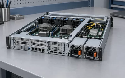
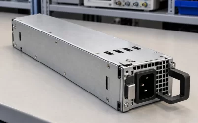
Photographs of a supply with no trailing wires can be misleading. A hot-plug server module commonly slides into a guided bay, where contacts on its rear edge mate with a receptacle in the chassis. That receptacle may sit on a PDB, a server board, or another platform-specific assembly. The technician replaces the module, but the fixed mating half remains in the host. The entire output connection therefore includes both halves and their alignment hardware, not merely the visible metal on the removable unit.
A cabled assembly presents a different boundary. The supply or a downstream PDB may have permanently attached conductors, detachable output ports, or a fixed board connector leading to a harness. The cable can move the electrical delivery point several centimeters or farther from the converter. The receiving board, cable assembly, and terminations become part of the power path. A bare module and a module-plus-harness may be sold under similar descriptions while requiring different host hardware.
In some rack systems, a PSU docks into a shelf that exposes power and return as busbar contacts. This changes the mechanical datums, joint pressure, insulation, and service boundary. The three arrangements are not interchangeable simply because they supply the same nominal DC voltage.
| Output arrangement | First mating boundary | What the integrator receives |
|---|---|---|
| Removable card-edge module | Module edge to host receptacle | Power and possibly control contacts on a defined board interface |
| Cabled supply or PDB | Connector or terminated lead to harness | Power delivered to a board at the end of a routed assembly |
| Power shelf with busbars | Module-to-shelf joint, then shelf-to-rack bus joint | A distributed DC bus with separate joint and insulation requirements |
Blind mating joins a pair of mechanical systems
In a removable module, the first output connection is usually made by the motion that seats the PSU in its bay. Guides, stops, latches, and connector float determine whether the contacts arrive at their intended positions without side-loading the receptacle. A candidate with the right outline but a different card-edge geometry may seem close enough to insert while failing to make reliable contact. Reversing the problem is equally dangerous: a matching connector silhouette does not establish the functions assigned to its contacts.
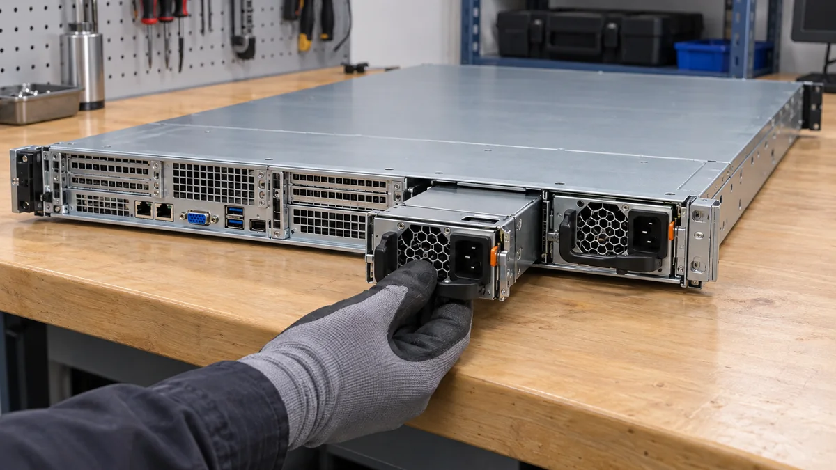
Power contacts normally share the output current across multiple conductive paths, with corresponding return contacts. A connector rating cannot be inferred by multiplying a generic per-contact number by the visible contact count. Contact distribution depends on the exact connector system, how its contacts are allocated, mating quality, temperature, board copper, and the manufacturer’s conditions. A partially seated module can concentrate current in fewer effective contacts and develop local heat even when the PSU’s electronic output remains regulated.
One official server example makes the architecture concrete without creating a universal pinout. Intel R1000BB Technical Product Specification, Revision 2.0, section 3.3.1 describes a removable supply with a card-edge output mating to a server-board or PDB receptacle. Its documented interface carries power and communication signals on the same physical connection. That is evidence for this particular platform, not permission to assume that another manufacturer’s similar-looking card edge has the same contact map or electrical behavior.
Within one host, one PSU may dock to a server board and another to a PDB. For the surrounding source-to-load interfaces, see Powernexu’s server PSU connector interface map. Here, the replaceable module’s output is only the start of DC delivery.
A harness relocates the power delivery point
Cable harnesses are useful when the receiving board cannot sit at the PSU bay or when one distribution board feeds several separated load zones. A PDB can have a compact power connector close to the PSU and longer leads toward the motherboard, drive backplane, fan board, or expansion area. The harness provides routing freedom, but every conductor, crimp, detachable plug, and board termination contributes resistance and consumes space. A photograph showing the right number of plugs cannot establish that the harness suits a particular chassis.
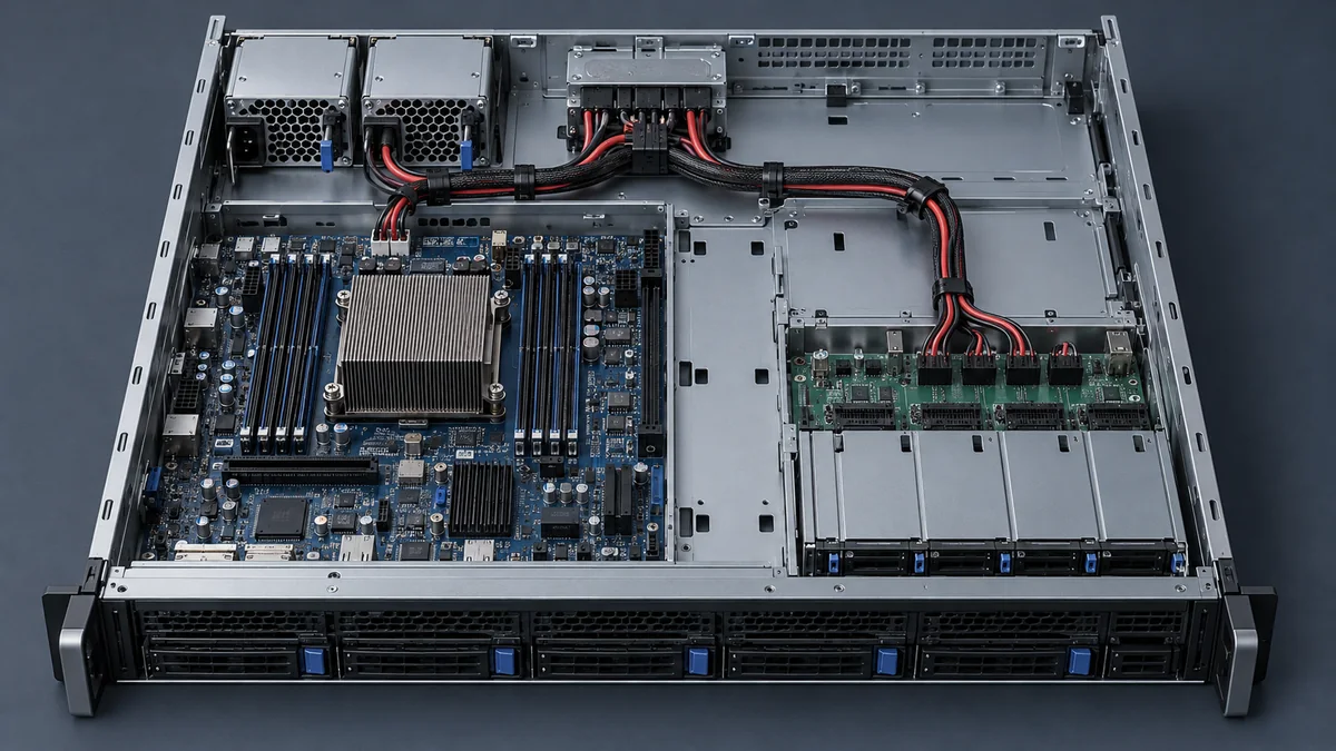
For example, Intel’s H2000G chassis specification identifies two power-output cables from each PDB to the chassis backplane and a separate cable for power-management signals. Its output connector table assigns multiple contacts to the main supply and return. This is a useful reminder that a harness can separate high-current delivery from control wiring; it is not a pinout for unrelated systems. The topology also shows why asking for “the PSU output connector” may not identify a single purchaseable part.
At the load end, the harness may terminate at a board input rather than at a CPU or storage device directly. That board may generate lower voltages locally or distribute the incoming bus to other branches. The connector name printed on a motherboard therefore describes the receiving side, not necessarily a wire that emerges from the PSU itself. A replacement search must follow the exact path through the host assembly instead of matching a familiar connector name in isolation.
Routing matters electrically. A long loop adds resistance and inductance; a tight bend can stress a termination; a harness in a fan path can raise temperature. Where the wire assembly is a separate service part, both PSU and harness must support the intended load.
Busbar output replaces flexible routing with a controlled joint
A busbar shelf replaces a bundle of long power leads with substantial conductive members and defined mating joints. That can be attractive when many modules feed a common rack-level bus at high current. The module-to-shelf contact and the shelf-to-rack contact are separate interfaces; both need suitable alignment and return paths. The busbar may carry the bulk power while management and auxiliary functions use another connector or board.
The Open Compute Project V2 Power Shelf Specification (dated January 5, 2015), sections 21.2.4 and 21.3.1 is an example, not a template for every data center. It describes module output connectors mating through contacts to shelf busbars and a separate positive-and-return output pair toward the rack. The engineering implication is that a busbar connection is still a connector system with joint resistance, mechanical tolerance, insulation, and temperature behavior. It does not eliminate the need to know where power passes from one manufactured assembly into the next.
A busbar’s fixed geometry can simplify a standardized rack while making a server retrofit impractical. A cabled PDB can route around an obstruction; a shelf-to-rack busbar must meet its mating geometry. The choice belongs to the host architecture, not to the voltage label.
The return connection is not spare metal
DC power reaches a load only through a complete loop. The main output conductor or contact carries current toward the load, and the return path carries it back. A diagram that shows a positive bus but omits its return hides half of the operating circuit. In a multi-contact output connector, both sides of the loop need the correct allocation and sound terminations. The safety-ground bond has a different purpose; it should not be treated as an undocumented substitute for a designed DC return.
Consider an illustrative 12 V branch carrying 40 A. If the combined resistance of its forward and return connections is 4 milliohms, the loop drops 0.16 V and dissipates 6.4 W at that current. These are hypothetical numbers, calculated from voltage drop equals current times resistance and loss equals current squared times resistance. They are not a permissible drop or connector rating. They show why a small resistance at a high-current output can warm a local joint while a PSU reports a normal voltage at its own terminals.
The position of a voltage-sense connection changes this picture. Some platforms sense at or beyond a distribution board so regulation can compensate for part of the path loss. Others regulate at the PSU output and accept an allowed drop downstream. A sense wire is not a parallel power conductor, and remote sensing does not cure an overheating contact or an inadequate return path. It can even make a poorly understood replacement behave unexpectedly if the sense pickup or control relationship changes. The exact sense arrangement must come from the specified system, not from the visual appearance of a connector.
Power, standby, and control may share a shell or travel separately
The connector called an output may contain more than the main DC bus. A platform can route standby power, enable, power-good, current-share, remote-sense, presence, or management connections through the same card-edge assembly. Another platform may put those functions on a separate signal connector or cable. An identical main voltage does not guarantee the server can start, report PSU status, or maintain its intended power policy when those auxiliary connections differ.
A thick cable may carry power while a slender adjacent cable carries required control signals; a card edge may combine both. Intel’s H2000G example separates main output from control, while its R1000BB example combines power and communication on the module edge. Neither arrangement is universal.
Standby power also makes the word “off” ambiguous. A server may have an auxiliary rail available before the main output is enabled. The visible fan state or front-panel indication does not prove every output contact is de-energized. Whether a standby rail comes directly from the module, is converted on the PDB, or is distributed elsewhere varies by platform. A replacement intended for the same bay must preserve the host’s documented behavior, including this sequencing, rather than only the continuous main-output rating.
A separate management cable may be a required control path even when the heavy power wires look complete. The assembly definition should distinguish main power, DC return, auxiliary power, control, and monitoring. For a replacement, the host-approved assembly revision is safer than a generic translation from connector shape.
Follow the output to its first real load
Describe a server power supply output connection as named mating boundaries: PSU to host receptacle, receptacle to PDB or server board, distribution assembly to harness or bus, and finally to the receiving board. Some systems omit stages. The description must identify which assembly owns each connection and where power and return terminate.
For a hot-plug replacement, the most consequential interface may be the hidden one at the end of the bay. For a fixed supply, it may be the cable and its board-side mate. For a rack shelf, it may be the busbar joint. Those different answers explain why two supplies with the same nominal voltage and wattage can demand different hosts. The output is not complete at the converter’s case; it is complete only when its intended current reaches the designed receiving point and returns by the designed path.