A regulated power supply uses feedback to keep its specified output near the intended value under defined operating conditions. An unregulated supply does not provide that same active output-voltage correction, so its delivered voltage can vary with source and loading conditions. For industrial applications, the useful question is which stage must hold the voltage required by the receiving equipment, and where that voltage is observed.
A regulated upstream source does not automatically regulate every remote load terminal. Conversely, an unregulated intermediate converter can belong in an appropriate architecture when another documented stage provides the regulation the final load needs. Comparing regulated versus unregulated industrial power supplies therefore starts with the connected circuit, rather than treating either label as a complete statement about equipment performance.
Follow the branch that turns off
Imagine a fictional controller that remains powered while a second branch operates intermittently. Both branches receive energy through the same upstream conversion path. When the intermittent branch stops drawing current, the power arrangement enters a different load state even though the controller itself has not changed its task. The source and shared distribution can respond to that event.
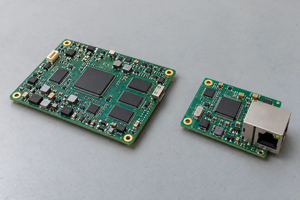
Suppose the proposed unregulated converter has a documented output characteristic that rises at lighter load. Turning off the second branch can then move the voltage supplied to the remaining controller. The amount and duration must come from the particular converter and implementation. This stipulated example is not a universal waveform or a claim that every unregulated product responds identically.
A regulated candidate can correct its observed output within its specified operating and dynamic limits. That does not mean the voltage remains mathematically constant at every instant. A transient excursion, a steady regulation tolerance, and a protection event describe different behaviors. The controller’s requirements determine which of those differences matter.
The branch event can also change wiring drop. If the two loads share part of a power or return path, removing one load changes the current through that segment. Voltage at the remaining receiver can move even while the source stays close to its setpoint. The observation therefore needs two locations: what the converter delivers at its defined boundary, and what the controller receives.
This is more revealing than testing only the machine’s busiest state. A lightly loaded or partially disabled state may expose a different source characteristic and a different distribution drop. Identify the branches that remain powered during standby, cleaning, maintenance, or an interrupted operating cycle. Their voltages deserve the same application attention as the fully active machine.
A branch need not be physically removed to change the load. Its controller can stop an actuator, place an interface into a lower-power state, or withhold an output command. The actual circuit can remain connected throughout. Describe those states using their electrical demand and required function rather than assuming that “connected” means fully loaded. This also keeps the investigation tied to ordinary equipment operation: an approved operating-state change can reveal a relevant difference without an improvised disconnection of live conductors or a deliberately introduced fault.
Feedback has an observation point
Traco Power’s January 22, 2026 explanation of regulated and unregulated converters distinguishes output feedback from conversion without that regulation loop. It also describes an unregulated converter followed by a local linear regulator as a possible combined arrangement. Those concepts support assigning regulation responsibility. They do not establish a particular module’s limits or prove that upstream regulation automatically compensates for cable loss.
A source regulating at its own terminals observes that boundary. The path beyond those terminals can contain connectors, protective devices, outgoing conductors, returns, and shared branches. Their effects are outside a terminal-only voltage observation. The word regulated does not give the source information about an unobserved point farther along that path.
Remote sensing, where supported and correctly implemented, changes the defined observation arrangement. It is a specific feature with wiring, adjustment, protection, and operating constraints. It should not be silently assumed from a regulated-output label. Nor does it eliminate conductor ratings, losses, or the requirements of other loads connected at different locations.
For a distributed cabinet, draw the intended regulated point beside each stage. A source can hold a common bus while a local converter regulates a separate rail near one receiver. Those are two deliberate functions. A second receiver connected directly to the bus does not inherit the local converter’s voltage behavior merely because it shares the cabinet.
The return reference belongs in that drawing. A voltage measured between a positive terminal and convenient chassis metal may describe a different quantity from the voltage across the load’s actual input pair. An apparent source-regulation problem can instead be a reference or distribution problem. Suitable measurements and the actual connection design distinguish them without treating protective earth as an ordinary load return.
Unregulated does not describe every other property
The regulation label concerns control of the output quantity. It does not, by itself, define whether a product provides galvanic isolation, protection, a particular conversion topology, or a supported environment. An unregulated converter can perform an assigned conversion or isolation role without supplying tightly controlled load voltage. Its documentation must establish the properties actually required.
Likewise, regulated does not mean linear, and unregulated does not mean that switching circuitry is absent. Regulation strategy and energy-conversion method are different descriptions. Avoid extending a simplified transformer-and-rectifier example into a universal inventory of every unregulated product. Compare exact architectures when their internal functions affect the application.
For a direct load connection, obtain the source’s output behavior over the relevant load and input conditions, including any minimum-load requirement. For a converter feeding another regulator, obtain the conditions that the receiving stage accepts. A nominal voltage printed on an intermediate module is insufficient to establish either relationship.
The load’s tolerance must also be documented. A motor, indicator, heater, sensor, or controller cannot be assigned a common percentage simply from its category. Operating voltage affects their functions differently. A device continuing to move or display a light is not evidence that it remains within its permitted conditions or delivers the required performance.
Protection remains a separate question. A regulated supply can leave its ordinary voltage-regulating mode when its documented limit or protection behavior applies. An unregulated source may also have protective functions. Neither the presence nor absence of voltage feedback alone establishes how a short, overload, startup demand, or returned energy will be handled.
Assign regulation to the load that needs it
Consider two proposed architectures for the fictional controller. One uses a regulated converter whose documented output serves the receiving circuit directly through an approved distribution path. The other uses an unregulated intermediate converter followed by a local regulator. The second arrangement assigns voltage correction downstream; it does not make that correction unnecessary.
Compare complete supplied functions. The local regulator needs an acceptable input from the intermediate converter during the relevant states. Its output must suit the controller, and its own startup, disable, fault, and thermal behavior remain part of the equipment design. Naming it a post-regulator does not establish those conditions.
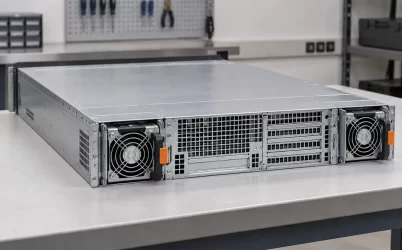
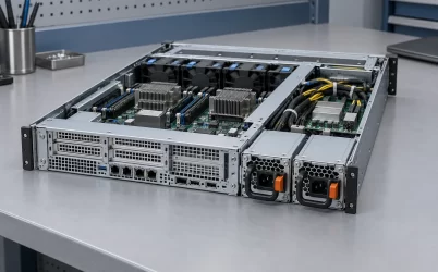
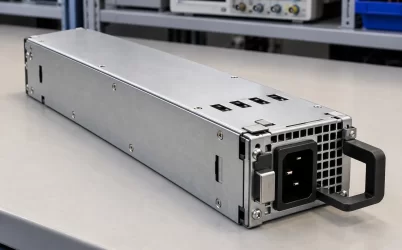
The physical placement can be useful when it puts the regulated boundary close to a particular load. It also creates another conversion assembly, connections, and operating dependencies. A picture of separate supply and controller hardware can illustrate that distribution of functions, but cannot identify the internal regulation scheme or prove a compatible connection.
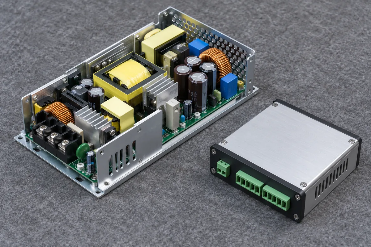
Do not repeat the local regulator on paper for a branch that bypasses it in hardware. If the intermittent load connects to the intermediate output, the intermediate converter sees that branch change directly. If both loads connect downstream of the local regulator, that regulator instead sees their combined demand. These are different loading arrangements even when the diagram uses the same two converter symbols.
One load’s regulation requirement can justify keeping it on a dedicated stage while another uses a differently specified source. That allocation should follow actual device and service requirements. A source suitable for a tolerant, stable load does not automatically become suitable for a newly added sensitive receiver. Equally, supplying one sensitive rail does not necessarily require replacing every upstream power component.
Cost and efficiency comparisons need the same boundary. A module-only figure for the unregulated stage excludes the downstream regulation it requires in this proposal. A complete-chain comparison should include the functions actually installed and their relevant operating states. No universal efficiency, size, noise, or price ranking follows from the two labels.
Separate a settling response from a changed operating state
Return to the branch turning off. A useful observation identifies the state before the event, the transition, and the settled state afterward. A source can have an acceptable final voltage yet a transition unacceptable to the receiver. Conversely, a brief change can remain within the receiver’s documented allowance while the new steady voltage is unsuitable.
Those outcomes demand different explanations. If the source-terminal voltage settles at a different value consistent with an unregulated characteristic, the architecture may need a different regulation arrangement. If source voltage is acceptable but the load-terminal voltage is not, inspect distribution and reference effects. These are investigation boundaries, not automatic diagnoses from one trace.
Observe the branch identity as well as total current. Two machine states can draw similar total power while placing current in different shared conductors. A convenient aggregate meter can therefore conceal the distribution change affecting the controller. Retain the actual connected population and return routes in the observation record.
Measurement speed must fit the question. A slow display showing the voltage after the branch stops cannot establish the shortest excursion during that event. A high-speed trace without a defined voltage reference or receiver criterion is also incomplete. Qualified personnel should choose appropriate instruments and connection methods for the installed equipment.
A single no-load check has a narrower use. It describes one operating condition and can expose a relevant output characteristic, but it does not establish the complete loaded behavior. A successful full-load check is equally bounded. Use the states that distinguish the actual proposal, rather than assuming one extreme is universally the correct test.
A replacement can move regulation responsibility
A replacement source with the same nominal voltage can still change how the connected equipment behaves. Its regulation characteristics, minimum load, startup, protection, and supported interfaces can differ. Preserving a nominal label does not preserve the relationship between the source, local regulators, branch population, and receiving loads.
This becomes especially important when replacing an assembly with a simpler module. An existing board may contain local regulation that is absent from the offered replacement, even if both product descriptions advertise the same output voltage. Conversely, an apparently redundant downstream regulator may be performing a deliberate load-specific function. Identify that function before removing it.
Keep the installed responsibility clear: which stage corrects the common bus, which stage corrects each local rail, and which receivers rely directly on a source’s unregulated behavior. Associate those functions with the actual product identities and connection arrangement. A later branch addition should revisit the affected relationship rather than inherit permission from the old population.
For industrial equipment, regulated versus unregulated is therefore a choice about where voltage control is needed and how the complete circuit provides it. A regulated source must still be evaluated at its stated boundary and conditions. An unregulated stage must have a load or downstream arrangement that accepts its documented behavior. The branch that turns off is useful evidence because it reveals whether that responsibility remains fulfilled when the machine stops drawing power in one place but still needs dependable voltage in another.