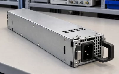
The Gospower G1136-1600WNA is a 1,600 W P185-series Platinum CRPS server power supply. That identification is supported by Gospower’s P185 listing and an exact-model 80 PLUS test report. The important procurement boundary is narrower: the report measures efficiency at 230 V nominal input, while an MSI MS-S322 approved-vendor list separately specifies a 1,000 W maximum at 100–127 V and a 1,600 W maximum at 200–240 V for this exact model in that platform. Those platform-specific figures should not be turned into a universal manufacturer derating curve. For a replacement or new server design, match the exact suffix, input-dependent output rating, host approval, and physical interface before turning the catalog entry into an approved part number.
The exact suffix connects three otherwise different records
G1136 is a family identifier, not a complete purchasing identity. Gospower’s P185 page shows several G1136 power levels, including 550 W, 800 W, 1,200 W, 1,300 W, and 1,600 W versions. A search result or warehouse label that says only “G1136” therefore leaves the output class unresolved. The suffix 1600WNA is the useful starting point for matching a manufacturer listing, a physical unit, a test report, and the server’s approved-parts list. A different suffix should be treated as a different item until the host vendor confirms interchangeability.
The Powernexu G1136-1600WNA product record describes a hot-pluggable 1,600 W module with a 185 × 73.5 × 40 mm envelope. Gospower identifies the exact model in its P185 Platinum CRPS family and publishes that family envelope. Its family page allows +12 V or +12.2 V output; the exact delivered unit and revision therefore need a controlled electrical specification before a nominal setpoint is assumed. These records independently support the category and nominal mechanical size. Neither listing supplies a controlled drawing of the mating connector or a server-specific approved-module declaration. A module can slide into a bay yet fail to mate correctly with the power distribution board, latch securely, report correctly, or operate within the host’s thermal arrangement.
The exact model also appears in an independent 80 PLUS verification report. The report names G1136-1600WNA and a rated output of 1,600 W. It is especially valuable because it gives actual test conditions and measured electrical results rather than a short product description. It does not replace the manufacturer’s electrical specification: an efficiency report is written to characterize conversion efficiency at stated test points, not to enumerate every permitted operating condition, connector signal, firmware behavior, and derating rule. Record its test date and tested model alongside the production part’s revision; a shared model string is a strong lead, but traceability to the delivered hardware still matters.
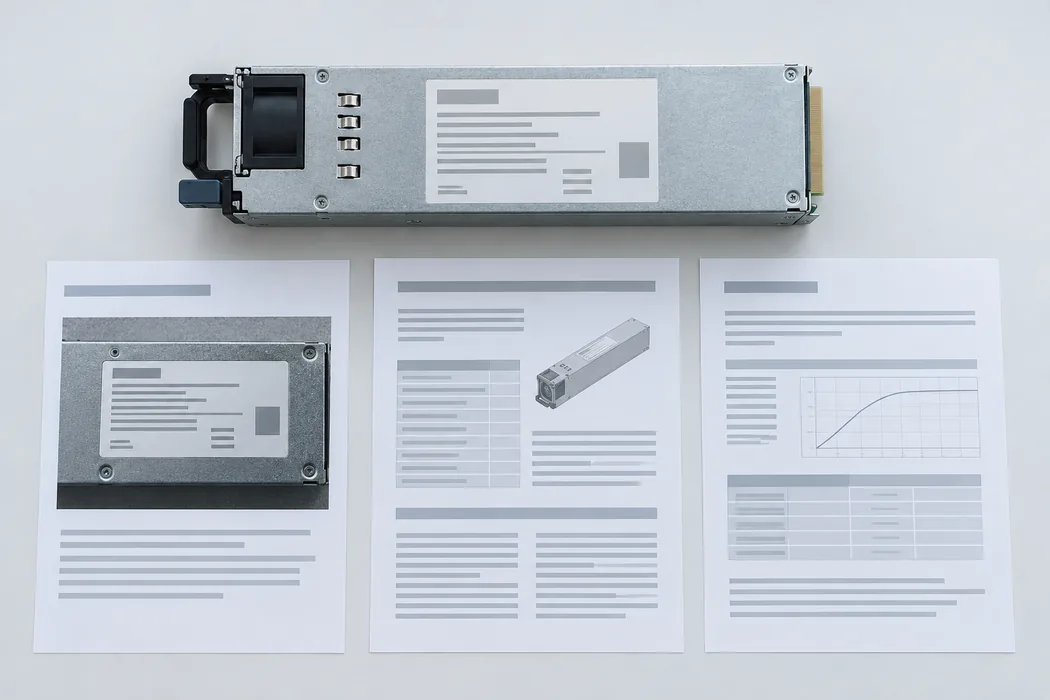
What the 230 V efficiency report can establish
The 80 PLUS verification report for G1136-1600WNA says its measurements were taken at 230 V nominal and 60 Hz. At the 100% load point it records 1,608.95 W DC output and 1,747.40 W AC input, with 92.08% measured efficiency. At 50% load it records 806.29 W DC output and 94.39% efficiency. These figures establish the measured performance of the submitted sample at those specified conditions; they are not promised efficiencies at a different AC voltage, ambient temperature, or server airflow.
The report’s 10%, 20%, 50%, and 100% load rows are test points, not four selectable operating modes. The tested unit’s efficiency changes with load, so applying the 50% figure to a fully loaded server would understate the expected conversion loss. At the full-load test point, the difference between reported AC input and DC output is about 138 W. That arithmetic describes the report’s measured point and the power that did not appear as DC output; it should not be pasted into a rack cooling plan as a guaranteed heat figure for every installation. External fan accounting, inlet conditions, and unit variation need the relevant design data.
The rated-specifications block in the report lists 100–127 V and 200–240 V input bands and input-current figures of 13.8/9.6 A. The testing note, however, places the reported efficiency measurements at 230 V nominal. These two parts of the same report must be read together. A listed low-line band establishes that the sample’s rated input information included that band; it does not show a 1,600 W low-line output test in the report. Powernexu lists a broader 90–264 V input interval. More usefully for one identified host, the MSI MS-S322 approved-vendor list gives 1,000 W maximum at 100–127 V and 1,600 W maximum at 200–240 V for G1136-1600WNA. That is platform-specific integration evidence, not a complete Gospower power-versus-input curve or proof of behavior at every voltage in Powernexu’s stated interval.
Input acceptance is not a full-power map
The Powernexu product page presents 90–264 Vac and 180–300 Vdc support in its overview, while its compact technical table gives 90 and 264 V as minimum and maximum input values. Gospower describes the P185 family as accepting AC plus high-voltage DC, but its public family page does not map this exact module’s output rating to every voltage in either source type. That mismatch in detail is a reason to request a controlled specification, not a reason to choose whichever number is most convenient. In a deployment record, write the supply voltage and source type beside the desired output power.
Consider a server planned for 1,300 W of maximum DC demand from its PSU assembly. On a high-line rack feed, the exact-model 80 PLUS report provides a measured point near full output at 230 V. That still does not approve this module for the host, but it makes the high-line output claim more concrete. On a 110 V staging bench, the same report gives no measured 1,600 W output point. If the system is qualified only on a high-line source, a successful boot at 110 V cannot establish that it will carry a production peak or survive the loss of a redundant partner on that bench.
The practical question is whether the manufacturer’s continuous-output table covers the actual line voltage, input frequency, inlet temperature, and airflow variant. A host vendor may also impose a lower system limit because of its PDB, connector, or cord. At high output, those downstream components and the branch circuit are part of the operating envelope. The catalog’s “1600 W” cannot be used as a standalone permission to draw 1600 W through a server whose power path was approved for less.
A separate DC-input path needs equally specific documentation. A range printed in a marketing section does not define input connector pinning, polarity, protection, permissible bus transients, or the behavior during source transfer. It also does not mean that AC and DC should be connected simultaneously. Treat the AC and high-voltage DC possibilities as distinct system configurations, each with its own approved power source and installation instructions. If the controlled data for the exact revision is unavailable, the safer procurement record is “DC option pending confirmation,” not an assumed operating range copied from a family page.
The 12 V figure belongs to a system power path
Powernexu lists a 12 V main output and 133.3 A maximum current. The MSI MS-S322 list instead describes +12 V at 132 A for its 200–240 V configuration. At 12 V, that main-rail current corresponds arithmetically to 1,584 W; the list also identifies a separate 12 V standby output. The 133.3 A seller figure should not be treated as the manufacturer-confirmed current for the offered revision. The 80 PLUS report shows the tested sample near full load at roughly 12.03 V and 131.65 A on the main output, plus a small standby load. That is a laboratory operating point, not a replacement for the manufacturer’s current-limit and transient specifications. It also does not reveal how much of the PSU’s output the server’s motherboard can actually receive after the backplane and distribution losses.
At more than 100 A, the physical path from module to load deserves attention. Contact resistance produces local heating; uneven seating or a connector with a different plating or contact pattern can concentrate it. The PDB copper, protective devices, bus bars, and output cables must be rated for the intended continuous and peak currents. A test that only confirms a module powers on may miss a thermal problem that emerges after hours near peak load. Conversely, a product page’s current number should not be read as permission to operate every compatible-looking connector at that current.
The MSI MS-S322 list describes a 12 V standby output at 2.1 A, while the Powernexu page additionally claims PMBus 1.2 capability without a supplied exact-model protocol document. These functions can matter in a managed server: standby power may support the BMC and power-control logic while the main rail is off, and monitoring can report operational state where the host implements the matching interface. The public page does not establish this module’s exact signal pins, command set, or host integration. A server may expect a particular address, sequencing, fault convention, or vendor extension. In a replacement plan, record the host’s approved module list and power-management firmware level, not merely “PMBus supported.”
Gospower’s P185 family description also mentions fan reversal. A reversible option is useful for chassis with different air paths, but a family capability does not show that every shipped G1136-1600WNA revision can be reconfigured in the field. Air entering from the wrong side can starve the PSU or disturb nearby components even when the electrical interface works. Obtain the ordered airflow direction and compare it with the chassis’s intended inlet-to-exhaust path. Do not infer direction from a product photo, because the visible grille may be an inlet in one assembly and an outlet in another.
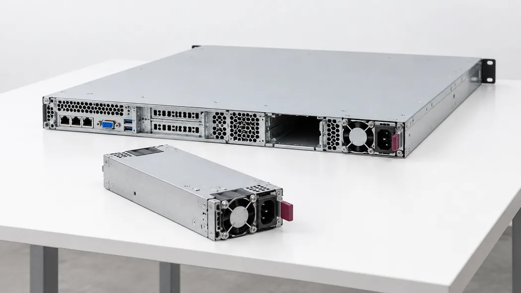
Host approval outranks a family resemblance
The MSI MS-S322 System Component AVL lists G1136-1600WNA as a passing 1,600 W redundant PSU option for that platform. That is useful evidence that the exact model has been used in a server context. It is not an approval for other MSI systems or for a different vendor’s chassis. Even within a listed platform, approved-vendor entries can depend on a part revision, chassis option, backplane, or firmware combination. The strongest replacement evidence is the target server’s own controlled parts list and service document, tied to the physical label on the module being ordered.
For a two-module redundant server, capacity must be evaluated after one module is lost. If the host needs 1,200 W from its 12 V path during a defined peak, the surviving module must carry that demand at the installed input and thermal condition, with the host’s distribution losses and transients accounted for. Two 1,600 W labels do not create 3,200 W of protected load in a 1+1 design. This is a system-topology calculation, not a separate specification published for the G1136-1600WNA. The host may also limit load after a fault, and that behavior belongs in the server’s operating documentation.
How to write a defensible spare-part record
A useful spare record names G1136-1600WNA exactly, identifies the manufacturer and ordered revision, and points to the target host’s approved-module entry. It records the site’s AC or DC source, the permitted output at that source, the mechanical and electrical interface drawing, the airflow variant, and the service part identifier printed on the delivered module. A document date or revision number makes later changes traceable. If one of these fields is unknown, mark it unknown; filling it from a neighboring G1136 model would hide the actual uncertainty.
The 80 PLUS report can sit in that record as evidence for the stated sample and test condition. The Powernexu product page can identify the offered item and public headline specifications. The Gospower page can corroborate the P185 family and nominal format. None of those three documents alone can authorize an unlisted host or establish the complete low-line power envelope. Keeping their roles separate makes the record easier to audit after a field failure, a platform revision, or a change in rack feed.
This distinction has an immediate operational benefit. If an emergency spare is selected because it is the right size and says 1,600 W, a technician may discover the mismatch only after insertion, when the server rejects it or derates under load. A properly identified spare can be checked against the host and feed before it reaches the rack. For G1136-1600WNA, the public evidence supports a real Platinum CRPS product and a measured 230 V full-load result. The MSI MS-S322 list documents a 1,000 W low-line maximum for its approved configuration; a complete manufacturer derating curve and approval for any other host still require controlled documents.