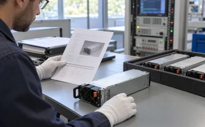
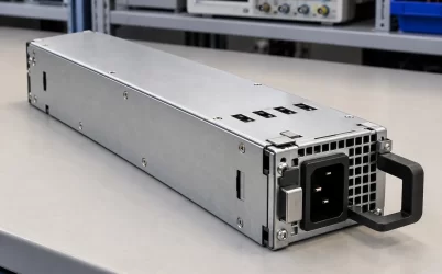
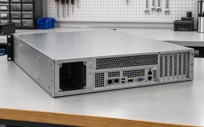
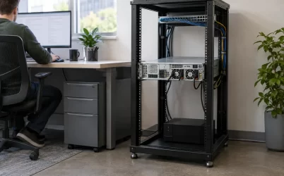
A 550W 24V industrial AC-DC power supply may require airflow before it can support the load used to select it. In an embedded machine, the fan, controller and 24 V load do not necessarily start together. Trace which rail runs the fan, what proves that air reaches the supply, and what removes permission for high load after a reset. The resulting sequence belongs in the equipment specification alongside output power.
Decide what is allowed to start without cooling proof
Start at the machine rather than the supply connector. List everything that receives power as soon as the source is available, including control electronics, branch converters and equipment waiting for a run command. Then identify the loads that can remain disabled while the fan starts. Some drives energize their input electronics when a feeder closes even if software has not requested motion. A load command that holds the motor still does not necessarily prevent the drive from drawing startup current.
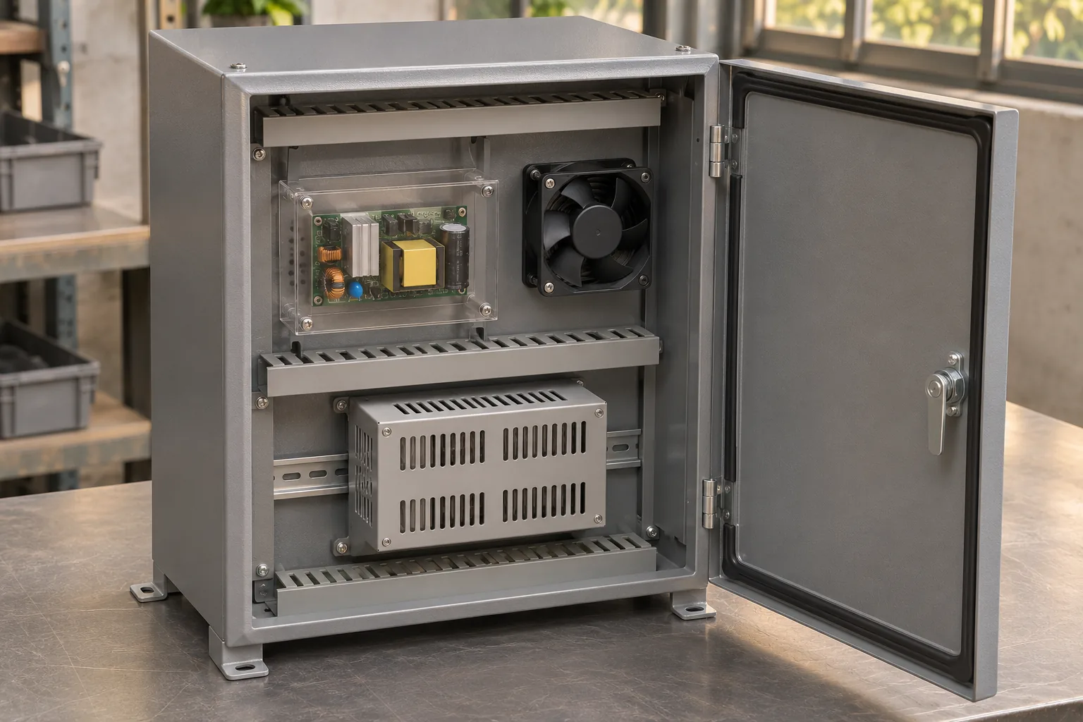
Suppose a cabinet needs 260 W while its controls initialize and 500 W after two mechanisms become available. These are hypothetical DC demands measured at the supply output, including the loads downstream of any conversion stages. At a nominal 24 V, they correspond to about 10.8 A and 20.8 A. A feeder that closes automatically at first power can erase the planned 240 W separation between these states. The designer should identify which physical or documented control action holds back that demand, and what happens to the action when its controller loses power.
A manufacturer’s open-frame datasheet illustrates why the two states need separate rules. It publishes different output limits for the 24 V variant under convection, conduction and forced airflow, and specifies a fan output separately from the optional standby and remote control functions. These distinctions identify the interfaces to verify. The datasheet does not establish when the fan output becomes available relative to the main output. Obtain that sequence for the exact delivered option before relying on the fan connector as the means of reaching full load.
Input voltage can impose a second limit even when cooling has been qualified. The datasheet’s fan-cooled curve falls from 550 W at 115 VAC to 430 W at 90 VAC and 360 W at 80 VAC. At the 90 VAC point, verified airflow still leaves the hypothetical 500 W state outside this example’s input-dependent envelope. If the host is allowed to restart from an input source that can settle at 90 VAC under load, a cooling indication cannot grant high-load permission by itself. Establish the required input envelope for the high state and record how the equipment enforces or verifies it. Those numerical limits belong to the cited example.
The same sheet specifies separate cold-start restrictions below 0°C and below 90 VAC. For example, its stated switch-on load ceiling at 85 VAC between −10°C and −30°C is 350 W, and the cold-start note specifies a five-second interval before applying full load. Read that interval alongside the applicable steady-state input derating. Elapsed time does not remove a continuous power limit, and the example does not establish a timer setting for a different supply or enclosure. If both limits can apply at the installation, document the allowed switch-on load separately from the eventual load and the conditions that release it.
The 260 W example must likewise be qualified under its own input, temperature and installation conditions. A headline convection rating does not establish permission inside an enclosure with a stationary fan, a closed access panel or a hot neighboring subsystem. Record the operating envelope for the startup state separately from the one for 500 W. If the low state requires airflow too, another source or a different architecture must establish cooling before the machine supply is asked to carry that load.
Follow the fan supply through first power-up
An auxiliary fan output looks like a short route from the power supply to the fan. Before using it as part of the enable sequence, determine when it is present, what its startup current allowance is, and how it behaves when the main output is disabled or the input rides through an interruption. The fan’s continuous input rating alone does not answer those questions. Check the fan’s startup and restart specifications together with the limits of the source that drives it. A source can support a fan after it is running and still fail to start it under a particular installation condition.
Consider two conceptual power paths. In the first, the main output starts early and supplies only the permitted low load. The fan starts from a documented fan output, the controller verifies the installed cooling condition, and only then can the downstream feeders enable their high-load equipment. In the second, a separate supply provides fan and controller power before the main converter is asked to run. That can simplify the dependency, but it introduces a separate source whose failure and recovery must be coordinated with the high-load permission. Neither arrangement is implied by an auxiliary-output label.
A circular dependency occurs when the command that enables the main supply waits for the fan, but the chosen fan output is present only after the main supply is enabled. Increasing a software timeout cannot make either side of that dependency start. Resolve it with evidence about the actual output behavior or choose an architecture that allows the fan to run independently. If the converter documentation leaves the relationship open, measure the ordering on an appropriately instrumented approved test assembly and obtain confirmation for the intended revision before making it a production requirement.
Draw the low-load and high-load paths separately on the cabinet schematic. Label the power source for each controller, its reset state, and the point where the high load loses permission. If a control output powers up enabled before firmware configures it, the wiring or downstream control design has to account for that interval. If a latched relay or persistent software setting survives a reset, decide how a fresh start clears the old permission. A sequence that is valid only after every controller reaches its normal state leaves the startup interval uncontrolled.
Separate fan motion from qualified airflow
A fan-speed signal can be a useful runtime indication. It tells the machine that a monitored rotor is turning under particular conditions. It cannot alone show the flow across a supply’s heat-producing parts. An incorrectly installed fan can turn while driving air in the wrong direction. With a blocked filter or a poorly sealed duct, the rotor can turn while the flow through the intended path falls. This is why the OEM airflow condition belongs to the installed arrangement rather than the fan’s unrestricted catalog rating.
Separate commissioning evidence from the signals available on every startup. Commissioning qualifies the relationship between the chosen fan, installed duct and airflow condition at the supply. Runtime supervision then checks the conditions that the machine can actually observe, such as speed, fan command, a representative flow or pressure signal, or a relevant temperature when the design permits it. A pressure switch also has limits. Its reading depends on where the taps are placed and what the measurement represents. Greater pressure drop across a clogged filter is not evidence of greater cooling airflow.
During a normal start, the controller should qualify the required cooling condition before it releases the high load. Define how long the indication must be valid and what makes it stale. Base any time allowance on the fan, sensors, enclosure and validated sequence. A universal wait time would conceal the very problem being tested. During operation, a cooling fault may call for dropping a high-power branch, limiting load, or carrying out a controlled stop. That decision belongs to the installed machine and its permitted thermal response.
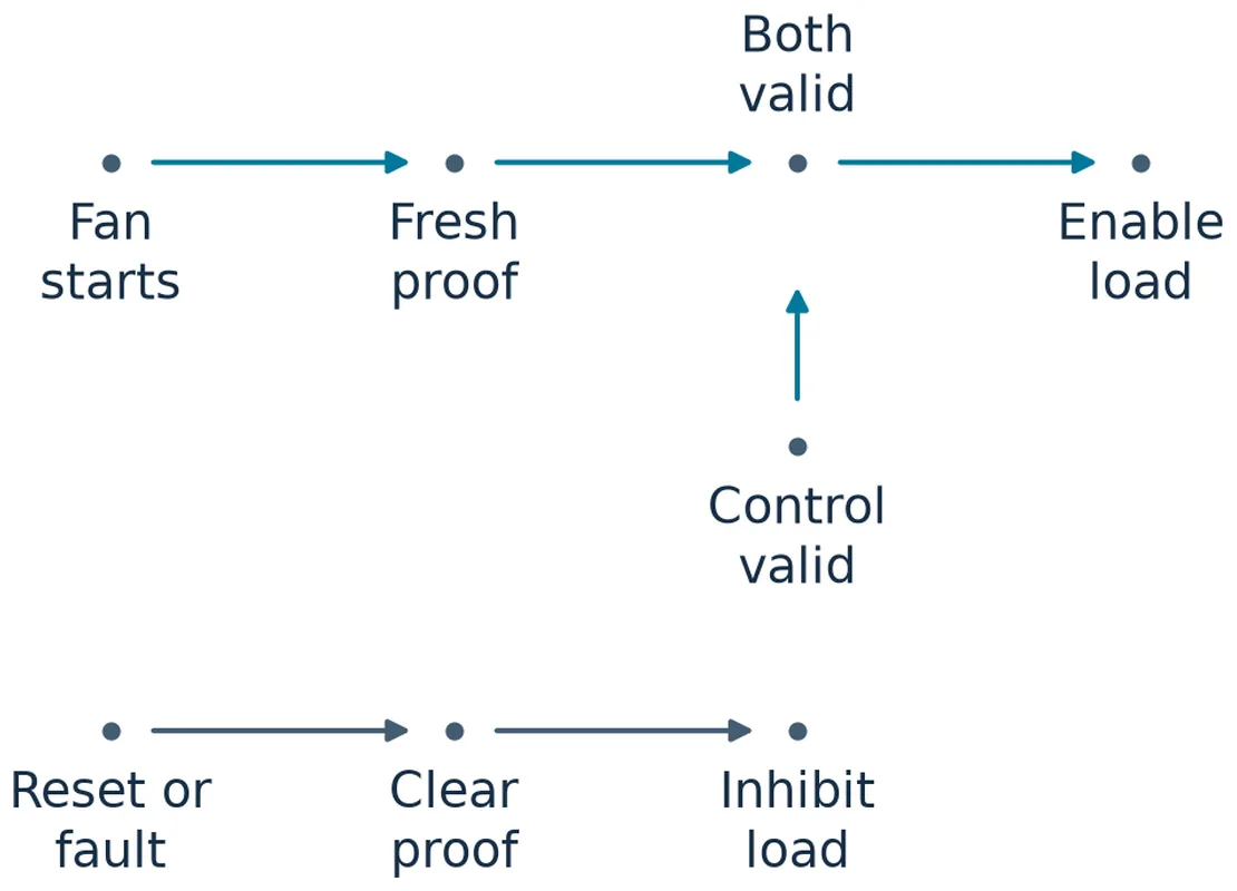
For an example in which 500 W is allowed only with airflow, the fault response cannot rely on the controller writing a log while the same 500 W demand continues indefinitely. It also cannot assume that reducing demand to 260 W is always an acceptable fallback. A closed cabinet after a fan failure can retain heat, and the stopped fan can obstruct a route that is open in a convection test. The low-load state after a cold start and the low-load state after operating at full output need separate evidence.
Test the transition as well as the running state
Commissioning should distinguish removal of AC, loss of fan power, loss of the fan indication, and a reboot of only the controller. These events need not occur together. An interruption can reset a controller even if stored energy or another source keeps the fan turning; a fan can stop while control electronics keep their state. The useful measurement is the order in which the relevant quantities and permissions change. Looking only at the final steady 24 V output can miss a brief interval when the high load was released before the cooling condition had been restored.
Capture the input or supervisory signal, controller reset state, fan power or speed, load enable, and supply output current on a shared time reference. When the choice depends on an airflow indication, capture that indication too. The comparison can then distinguish a fan that restarted from a controller that simply reused an old pass. Test a warm restart as well as the initial cold boot, because the cooling system may start from a different temperature and mechanical state.
Include the state where the fan runs but its reading is temporarily unavailable. For example, a controller may reboot while a separately supplied fan continues turning. In that case the machine needs to distinguish actual loss of cooling from a loss of evidence used to grant permission. The temporary response can be conservative in both cases without treating them as the same service fault. A log that records the inputs and their order helps a technician tell whether to investigate a fan feeder, a damaged sensing lead, or reset behavior. Neither a steady 24 V reading nor a single speed sample answers that question.
Questions for separate startup and recovery tests
| Test condition | Evidence the equipment needs |
|---|---|
| First application of power | High-load feeders stay inhibited while only the validated startup load is present. The cooling check becomes valid before the feeders are enabled. |
| Short input interruption | The controller establishes which signals remained valid, clears any invalid permission, and requalifies cooling before returning to high load. |
| Fan fault during a high-load state | The observed cooling fault leads to the verified rollback or stop. The protected machine reaches its allowed thermal and electrical state. |
| Controller reset with the supply still on | The high-load permission has a defined state through reset. The controller cannot use an old or invalid cooling indication to approve a new transition. |
Use these tests to evaluate the installed design, not as instructions to defeat thermal protection or interrupt live wiring. A planned fault simulation can be made at an appropriate supervisory interface on controlled equipment. If a measurement requires access inside an energized enclosure, use qualified personnel and the equipment maker’s approved procedure. The purpose is to show what the completed machine does before extrapolating from a bench observation.
Specify the parts that make the sequence possible
A purchase specification should state the required sustained current, the thermal condition at which it is needed and the expected startup demand. Then keep the fan output, any standby supply and the enable function on separate lines. Record which options provide those interfaces, when they are available during startup and recovery, and whether their loads count against other documented output limits. If an option affects the enable signal, require the order to identify that option and the receiving inspection to verify it. The same family description may appear on an offer whose auxiliary interfaces differ.
There is also a choice between an embedded board cooled by the host and an enclosed supply with its own cooling arrangement. The open-frame source can let the builder control where air travels and where the fan is serviced. An enclosed product may reduce some mechanical integration work, but it has its own inlet, exhaust and application conditions. Either option still needs a defined electrical load and a verified installation. A substitution should preserve the required output envelope and startup behavior, even where its cooling path or connector layout differs.
The release record should make it possible for a different technician to reproduce the result after a fan or supply is replaced. Record the selected revision, fan and duct configuration, tracked evidence for the controlled operating point, which state grants the high-load permission, and which conditions revoke it. On a finished machine, the most useful result is an observable event: the high-load feeder remains inhibited until cooling has been established and qualified. If the equipment cannot demonstrate that transition, the rating remains a supplier specification with an installation condition still to be satisfied.
Frequently asked questions
Can the fan run directly from the same power supply?
Yes, if the exact interface supports the fan’s startup and running demand and is available in the state in which the fan must start. The host still needs a verified means of keeping high load disabled until the installed cooling condition is qualified.
Can a fan tachometer replace an airflow measurement?
A tachometer can be part of runtime supervision after the installed flow path is qualified. For commissioning it does not establish that air crosses the right part of the board or that the required flow exists at the rated condition.
Should the machine restart automatically after a fan fault?
Use the equipment’s approved recovery policy and its verified thermal state. Return to the high-load state only when the machine has established fresh cooling permission and met any required reset or restart conditions.