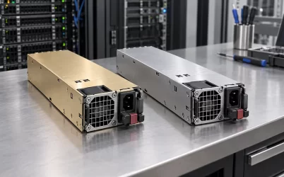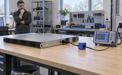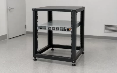
The G1508-2000WNA is listed by Gospower as a 2000 W, 54 V CRPS module for servers, storage, and networking equipment. Powernexu’s current product table, however, describes the same exact model as a 12 V, 166.6 A supply. That conflict changes the electrical architecture, so a buyer should verify the physical label and revision-controlled manufacturer datasheet before connecting the module to a host. This article explains what the published evidence supports, how a 54 V server power path differs from a 12 V one, and which design choices follow once the output rail is confirmed.
The published 12 V and 54 V descriptions cannot describe one output
The Powernexu G1508-2000WNA product page lists 2000 W, 12 V, and 166.6 A. Multiplying its stated voltage and current gives approximately 1999 W, so those entries are arithmetically consistent with one another. Yet Gospower’s exact-model listing places G1508-2000WNA in its 54 V CRPS T185H family and specifically says the output is +54 V. A 12 V host bus and a 54 V host bus require different downstream components. Neither the arithmetic nor a shared model string resolves which hardware a supplier will deliver.
The manufacturer page also states a 185 × 73.5 × 40 mm size, 90–264 VAC input, Titanium efficiency designation, and support for fan reversal. It lists certifications, but these summary statements do not replace an approval report for the exact shipped revision and market. A request form is offered for the specification sheet; the public page does not show a 54 V output-current table, pin assignment, power-versus-input curve, standby-rail rating, or current-share specification. The Powernexu table supplies 12 V current information but cannot be used to fill those missing 54 V details while the rail identity is disputed.
Before a purchase order describes this as either a 12 V or 54 V spare, request photographs of the complete unit and its rating label, the manufacturer’s controlled datasheet for the exact part suffix and revision, and an electrical drawing that identifies the main-output contacts. Compare the supplier’s document number with the label on the actual lot. If the documentation confirms a 54 V unit, correct the procurement record and host configuration accordingly. If it confirms a 12 V variant, obtain a written explanation of why the manufacturer’s public exact-model page identifies 54 V. That evidence trail is more useful than relying on a catalog title alone.
Why a 2000 W, 54 V rail changes the server power path
At the same delivered power, a higher distribution voltage reduces current in the segment before point-of-load conversion. For illustration, an ideal 2000 W load would correspond to about 37 A at 54 V, versus about 167 A at 12 V. These are simple P/V comparisons, not published G1508-2000WNA ratings; actual current depends on voltage tolerance, conversion loss, standby output, operating conditions, and the product’s continuous rating. The comparison still explains why a 54 V architecture can ease current density through a shared distribution segment.
That benefit comes with a different host design. Processors, memory, drives, and many accelerator circuits cannot simply be connected to a 54 V bus. The server needs appropriately rated downstream converters and a distribution board built for that input. A 54 V module may allow current to travel farther before conversion, but power lost in the converters, their cooling needs, and their fault behavior then become part of the platform design. The supply’s 2000 W marking is an upstream boundary; it does not describe how much usable low-voltage power emerges after every conversion stage.
A common mistake is to assume that the similar CRPS enclosure makes the 54 V unit interchangeable with a 12 V supply. Mechanical fit merely answers whether the body enters the bay. It says nothing about which contact carries the main output, how the host senses a module, whether the PDB tolerates the voltage, or whether the power controllers can manage it. A 54 V source applied to a board designed for 12 V may damage downstream circuits. Keep suspected variants physically segregated until the rail and mating interface are proven from controlled documents and the actual hardware.
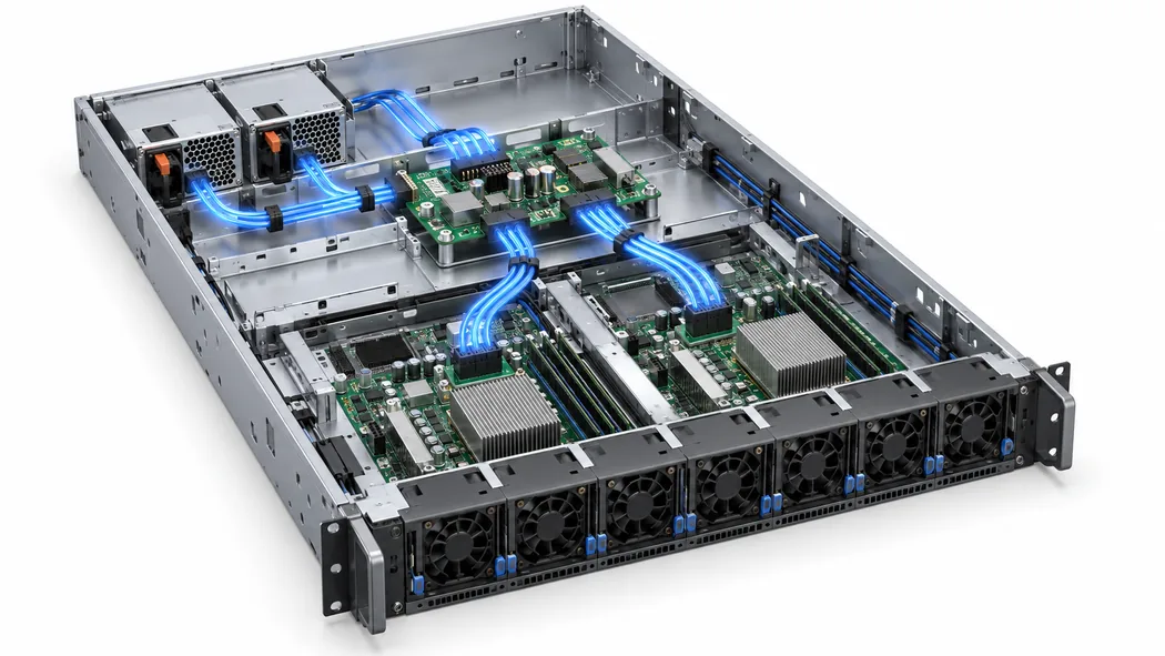
The illustration shows a generic distribution relationship, not the G1508’s verified internal wiring or contact layout. In a 54 V design, map each stage from module contacts to the common bus, protection, conversion, and final load. Record where power crosses a connector, copper plane, busbar, cable, or conversion boundary. At each crossing, the design must be rated for the applicable voltage, current, fault energy, and temperature. A successful connector fit cannot establish those electrical limits.
Specify the input and output conditions as a pair
The Gospower public page states a 90–264 VAC input range, but it does not say that 2000 W is continuously available at every voltage in that range. Some high-power supplies reduce output at low line or high temperature. Without a model-specific curve, the safe reading is that the listed input range describes permissible input, while available output at a particular feed remains to be documented. The distinction matters for facilities that alternate between different PDU circuits or operate equipment in regions with different nominal voltages.
For a proposed deployment, identify the lowest supported voltage at the PSU inlet under load, including transfer to a backup feed where applicable. Ask the supplier to state the continuous output power, output voltage range, maximum input current, and ambient or inlet-temperature condition at that voltage. A 2000 W label by itself cannot determine branch-circuit draw: AC input also depends on conversion efficiency and power factor at the chosen operating point. The Titanium designation is useful context, but it is not a single efficiency percentage that can be applied to every load and inlet condition.
The 54 V output also needs its own operating envelope. Request regulation range, ripple and transient limits, startup sequence, hold-up behavior, current limit, overvoltage response, and any remote-sense requirements. These are not generic values to copy from another T185H model. Their relevance is practical: a downstream converter may accept 54 V nominal yet reject a startup overshoot, a sag during failover, or a rail that moves outside its input window during a rapid load step. Design limits should be compared at the converter input after the distribution path, not solely at the module terminals.
Consider a hypothetical 1.6 kW collection of low-voltage loads. If downstream conversion were 94% efficient at that operating point, those converters would draw about 1.70 kW from the 54 V bus, before other distribution and auxiliary losses. The 94% figure is an illustration, not a specification for G1508-2000WNA or any particular converter. It shows why adding the downstream load ratings directly and comparing them with 2000 W can overstate headroom. Use the actual converter curves, duty cycle, and worst-case simultaneous loads to establish the bus demand.
The 54 V PDB and converters become the decisive components
With a confirmed 54 V source, the distribution board is no longer a passive substitute for a 12 V PDB. Its conductor spacing, component voltage ratings, connector assignment, switching or isolation elements, bulk capacitors, and fault protection need to match the higher bus voltage and the applicable safety design. The exact architecture may use a backplane, busbar, or power board; the manufacturer summary does not establish which. Ask for the host schematic or approved interface drawing instead of inferring the topology from the PSU outline.
Point-of-load conversion determines where current rises again. A conversion stage that takes power from 54 V and supplies a low-voltage accelerator branch can make the upstream path relatively moderate in current while the local branch carries much more. Board copper, connectors, and protection must be sized at the voltage and current of their own segment. It is misleading to use an approximately 37 A ideal source-side figure as the current rating for a 12 V downstream branch. Each branch has its own power and current budget after accounting for conversion loss.
Fault coordination also changes. A short on one downstream converter should be contained so it does not collapse the shared bus for every load, if the host’s availability requirement calls for that behavior. Whether the PSU shuts down, limits current, or retries depends on its actual protection design and the PDB’s devices. Those mechanisms need to be studied together because a protective element that opens too slowly can stress contacts, while one that trips too aggressively can turn a harmless workload transition into a server reset. The public G1508 page does not publish those timings or thresholds.
For a modular server, document how the BMC receives power-good, presence, fault, and telemetry information. Do not infer a PMBus version, command set, address, or connector pinout from the word CRPS. If the host controls input power to converters or caps accelerator demand after a PSU event, the signal sequence becomes part of the power design. A powered rail with an unrecognized module can still leave the system in an unsafe or unsupported operating state. Host and PSU control documents should agree on the actual shipped revision.
A redundant pair has one surviving 54 V capacity
Two 2000 W modules in a shared-bus system can offer capacity or fault tolerance, but the usable number depends on the required failure state. For a 1+1 arrangement that must continue at full load after either module is lost, the protected bus demand cannot exceed the surviving module’s allowed output at the relevant input, temperature, and airflow. Adding the labels to claim 4000 W of protected load would ignore the failure that redundancy is meant to handle. The bus and converter losses still belong inside that protected-load calculation.
Current sharing needs a host-specific answer. The presence of two matching physical modules does not prove they share equally, isolate faults correctly, or accept a mixed revision pair. A controller may need compatible identity and telemetry behavior before it permits full workload. When one unit is removed, the other sees a step in demand; the PDB’s bus capacitance and converter input limits influence whether that transition stays within the operating window. Ask for the supported pairing matrix and failover behavior, then test the actual host at representative load.
Use the same model name only after the physical module is identified
The immediate sourcing question is unusually concrete: what output is printed on the G1508-2000WNA that will arrive? Record the photographed label, serial or lot information, manufacturer document revision, and supplier part number alongside the host’s approved BOM. Inspect the complete enclosure, insertion guides, latch, connector location, and airflow direction, then compare them with the host drawings. Gospower says the family can support fan reversal, which makes airflow configuration another item to specify rather than assume from a product photo.
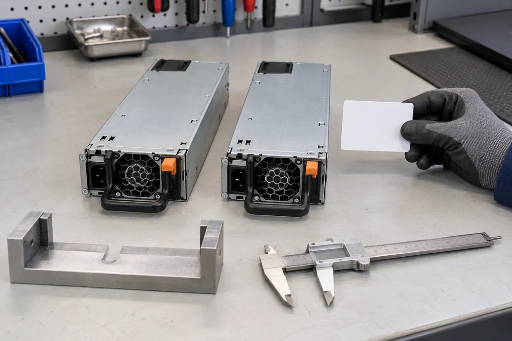
Keep the received module quarantined from 12 V spares while the published conflict remains unresolved. If an existing platform is genuinely 54 V, confirm that the delivered PSU’s standby and management connections match the host and that downstream converters are rated for the documented output window. If the installed platform is 12 V, a 54 V exact-model listing is a warning to stop the substitution until the supplier produces controlled evidence for the delivered 12 V hardware. A seller’s claim of “same 2000 W CRPS size” does not answer that question.
The 2000 W class can be attractive when a server’s measured and specified load fits within the module’s conditional rating, with sufficient margin for the required failure state. That is a platform-level assessment after rail identity, feed condition, distribution architecture, and service behavior are known. For G1508-2000WNA specifically, the first engineering decision is simpler and more urgent: resolve the 12 V versus 54 V discrepancy against the shipped label and manufacturer datasheet. Once that is settled, the appropriate 54 V or 12 V design path can be evaluated on its own evidence.