What is the maximum server PSU operating temperature? There is no single temperature that applies to every server power supply. A number printed in a module datasheet is meaningful only after you know where the air temperature is measured and under which input, output load, and cooling conditions the module can still deliver its stated power. A 50°C rating at the power supply inlet does not mean a 50°C reading at the processor, the rear exhaust, or somewhere in the room. It also does not necessarily mean full output at every input voltage. The useful answer is a conditional operating envelope for the exact PSU and host, not a universal thermal limit.
Where is “operating temperature” measured?
For a forced-air server supply, the temperature of the air entering the PSU is often the relevant environmental measurement. Texas Instruments describes server PSU operating temperature, in its thermal-management discussion, as ambient temperature at the PSU AC inlet where the fan is located. That description is useful because it points to a physical location, not merely a room thermostat. It is not a substitute for the definitions in the specification of the particular module you intend to use. Some assemblies have a different airflow direction or an inlet located elsewhere in the chassis.
Imagine a rack room held at 25°C while a cable bundle and a nearby exhaust stream warm the air entering one PSU to 35°C. Calling that supply a “25°C application” would conceal ten degrees at the place that matters to its intake. Conversely, a server management screen might display a board sensor at 40°C while cool air reaches the PSU inlet at 27°C. That board temperature alone does not establish that the power module has exceeded its ambient rating. The measurement point changes the answer.
Inlet air is also different from component temperature. Semiconductor junctions, transformer windings, electrolytic capacitors, heatsinks, and the air leaving the rear of the module normally run warmer than incoming air. Their individual limits are handled by the module design and its protection strategy. A product rated for a specified ambient inlet temperature is not claiming that every part inside stays at that temperature. The thermal rise between intake and internal components is precisely why the fan, ducting, loss distribution, and load condition matter.
When a server specification states a system operating ambient range, check whether it describes air at the server front, a room condition, or a point chosen by that manufacturer. A PSU module specification may use a different reference point. Neither reading can be substituted for the other without understanding the airflow path between them. The gap can be especially large in a densely packed rack or a chassis that pulls air from a rear plenum.
The maximum is usually attached to a power condition
Suppose a module sheet says “operating 0–50°C.” That phrase alone still leaves an important question: does the module supply its full nameplate output throughout that range? Some supplies do. Others require output derating above a specified ambient temperature, at low AC input, or at altitude. The usable output is then a curve or table, not the single wattage printed prominently in a catalog title. The exact curve must come from the applicable manufacturer documentation; borrowing a percentage per degree from another product would be misleading.
Input voltage can change the thermal situation before the air temperature changes at all. At lower input voltage, a converter may draw more current to deliver a given output. Input-stage conduction loss and connector loading can rise. Certain server PSUs explicitly publish different maximum output powers for different AC input ranges. Supermicro’s PWS-1K62P-1R quick specification, for example, lists 1000 W for 100–120 Vac, 1200 W for 120–140 Vac, and 1620 W for 180–240 Vac. Those are facts about that named model, not a rule for every server PSU. They illustrate why a high-temperature discussion must keep the specified input range alongside the temperature rating.
Output loading is the other half of the condition. At a lighter load, the module dissipates less absolute heat in many operating regions; at high load, internal loss and airflow demand increase. An efficiency figure measured at a particular load point is not a complete heat map. If the converter is 94% efficient while delivering 1000 W at a stated condition, the calculated input is about 1064 W and the conversion loss about 64 W. That calculation is illustrative, not a promise that the same efficiency holds at a hotter inlet, different input voltage, or different load. The datasheet’s thermal and output limits govern the real operating point.
A specification can also distinguish continuous operation from short-duration excursions. A server or rack environment permitted to experience an elevated temperature for a limited interval is not thereby approved to run continuously at that temperature. Likewise, storage and non-operating temperature ranges describe an unpowered product and should never be used as operating targets. Read the heading and footnotes around the number before interpreting it as a continuous, full-load PSU limit.
Why the management temperature may not answer the question
Server management software can report several temperatures: front-panel inlet, motherboard ambient, CPU, DIMM, GPU, drive backplane, and sometimes a PSU internal sensor. Their names may look similar, but they monitor different thermal paths. A BMC “inlet” reading near the chassis front may be useful for room-level monitoring. It can still differ from the temperature entering a rear-mounted PSU after air has passed over processors and memory. An internal PSU sensor is even less interchangeable with an inlet-air rating because it measures a component or board location after some thermal rise.
The distinction becomes practical when troubleshooting. If a PSU thermal warning occurs while the room sensor reads a comfortable value, inspect the local intake path rather than concluding the warning is false. A missing blanking plate, stalled fan, blocked perforation, rear hot-air recirculation, or neighboring equipment can heat or starve just one supply. Conversely, a high CPU reading does not by itself prove the PSU intake is too hot. It may point to a separate cooling bottleneck. The location and trend of each sensor matter more than a single largest number on the dashboard.
Redundancy changes the hot operating point
A redundant pair can make a temperature claim look safer than it is. Under normal sharing, two modules divide the electrical load. If one module fails or is removed, the surviving PSU may have to supply essentially the entire protected load. Its losses, internal temperature, and fan speed can change abruptly. The relevant maximum-temperature case is therefore not always the calm two-module state shown in a nominal installation. It may be the remaining module at the site’s hottest expected intake condition and the actual available input voltage.
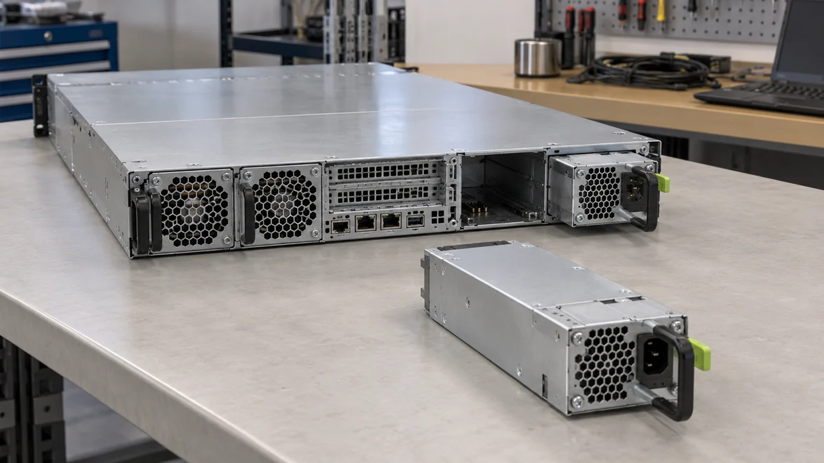
This is a capacity issue as well as a cooling issue. A pair of 1200 W modules in a 1+1 system does not provide 2400 W of redundant output capacity. The protected load must fit within what one module can deliver under the applicable electrical and thermal conditions. If its allowable output falls at high temperature or low line, that reduced value is the one that matters after a failure. The system vendor may impose an additional platform-level limit to protect connectors, backplane, or the server’s own thermal design.
Fan behavior in the failed-state configuration also needs careful interpretation. The missing module may leave an opening that changes pressure and recirculation; a blanking unit may be required. The surviving module may increase fan speed, while chassis fans respond to their own sensors. No single “PSU maximum temperature” figure captures all those host effects. The module rating and the system’s supported redundant operating envelope need to agree, particularly when the site expects service to continue through a module replacement.
Thermal shutdown is not the rated maximum
Over-temperature protection is a safeguard, not an operating target. A module can be designed to shut down when an internal component crosses a protective threshold. That threshold may be well above the recommended inlet-air limit, and it can vary by sensor location, load, component tolerance, and timing. The supply is not “rated” for operation up to the instant it trips. Running repeatedly near a protection event can still degrade stability and lifetime even if the output has not yet switched off.
Warnings can precede shutdown, but they are not universal thermometers either. A warning may indicate a hot internal sensor, excessive inlet air, a fan fault, or a platform-specific condition. Dell’s server event documentation, for instance, advises checking airflow and inlet temperature when a PSU temperature event is reported. That is a troubleshooting direction, not a published operating limit for every Dell or third-party module. The cause should be read alongside fan status, load, input, and local inlet conditions.
Altitude and airflow are conditions, not interchangeable temperature numbers
Air cools by moving heat away from internal surfaces. At higher altitude the lower air density can reduce mass flow for a given volumetric airflow, which may change the cooling available to a forced-air module. Manufacturer specifications sometimes state an altitude derating or a lower permissible ambient at elevation. Do not apply a generic correction to an unrelated PSU: the module fan, pressure resistance, heat distribution, and qualification determine its actual curve.
Airflow direction matters in a rack with mixed equipment. If a PSU expects cool air from one side while the cabinet delivers heated air from another, the nominal room temperature tells little about the air it receives. Dust and obstruction can reduce effective flow without visibly raising the room reading. For this article’s question, the key is not to design the entire cooling system; it is to recognize that the published temperature limit assumes a defined flow path. If that path is absent, the number is no longer being used under its stated conditions.
A temperature limit belongs to an installed system
A standalone module may have a broader environmental rating than the server holding it. If a hypothetical module were documented for full output to 45°C at its own inlet, while its host were supported only to 35°C at the specified system inlet, the assembled server could not be described as a 45°C system. These numbers illustrate the relationship; they are not specifications for a Powernexu or other named product. The opposite mismatch is possible too: the server front inlet can remain within its limit while local recirculation makes the PSU’s actual intake hotter.
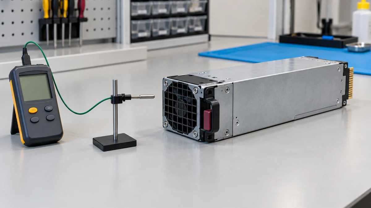
A small probe in the air entering the PSU, without blocking its grille, can reveal that difference. Its position matters as much as the reading: a probe beside a hot exhaust stream or touching the metal shell answers another question. So does an idle reading when the concern is continuous full output or the hotter single-survivor state of a redundant pair. Management sensors supplement a local measurement when their locations are known; they do not silently replace it.
If a module sheet says only “0–50°C” without defining the air measurement point, full-load behavior, or cooling conditions, it does not establish that the installed server can deliver full output at a 50°C PSU intake. The defensible limit comes from the module’s documented operating envelope and the host’s restrictions applied to the air that actually enters the supply. An internal sensor alarm or a room thermostat cannot supply those missing conditions.