G1236-3000WNA is a Gospower T265-series, 3000 W-class CRPS module with a published 265 × 73.5 × 40 mm enclosure and a +12.2 V main output. Those details matter because a Powernexu catalog entry for the exact model instead lists a 185 mm length and 12 V output. The manufacturer’s description and an independent photograph of a labeled unit support the longer body and 12.2 V rail. A buyer considering this module as a server spare should resolve the dimensional discrepancy before assuming that it enters a 185 mm bay. The full 3000 W rating also depends on the input-voltage tier; the name alone does not promise 3000 W from every outlet.
The model name identifies a power class, not a bay fit
The Powernexu G1236-3000WNA listing describes a 3000 W hot-pluggable module, 185 × 73.5 × 40 mm, with a 12 V, 250 A output and a 90–264 V input range. Multiplying 12 V by 250 A gives 3000 W, so the electrical entries form a plausible summary. Yet Gospower’s exact-model manufacturer page places G1236-3000WNA in the T265 Titanium series and highlights a 265 × 73.5 × 40 mm enclosure and +12.2 V DC output. An 80 mm length difference is too large to treat as measurement tolerance or a cosmetic revision.
The manufacturer’s English page contains a stray T185 description in its introductory paragraph, while its series name and highlighted dimensions say T265 and 265 mm. Its Chinese exact-model page likewise identifies a T265 series and 265 mm dimensions. A photographed G1236-3000WNA label in a detailed teardown identifies the same model; the measured unit is approximately 265 mm long. These sources make the shorter Powernexu entry suspect, but they do not prove that every historical or supplier-specific revision has identical mechanics. Request a current drawing and photographs of the actual orderable revision, including the entire side profile and the label, rather than trying to reconcile the entries by assumption.
There is a second, smaller electrical distinction. The manufacturer specifies +12.2 V, whereas the catalog rounds or reports the main rail as 12 V. In many server discussions, both may be described informally as a 12 V architecture. At the connector, however, the controlled voltage set point and tolerance govern system acceptance. A host designed around a particular supply range, current-share behavior, and power-distribution board cannot be approved by an informal shorthand. The 12 V and 250 A catalog figures also should not replace a controlled output-current table for the delivered part.
What the 80 mm depth difference changes inside a server
A CRPS module is installed along a guided path, not placed loose in a chassis. The bay rails, stop position, latch, output edge connector, and internal distribution board set the insertion geometry. If a host expects a 185 mm module, a 265 mm body may run into a fan wall, drive cage, motherboard component, cable assembly, or even the intended PDB position before its contacts engage. An external rear-panel opening of the right width and height does not establish compatibility. Conversely, a deep bay may have a connector positioned specifically for the longer unit, so a shorter module may fail to reach the contact system.
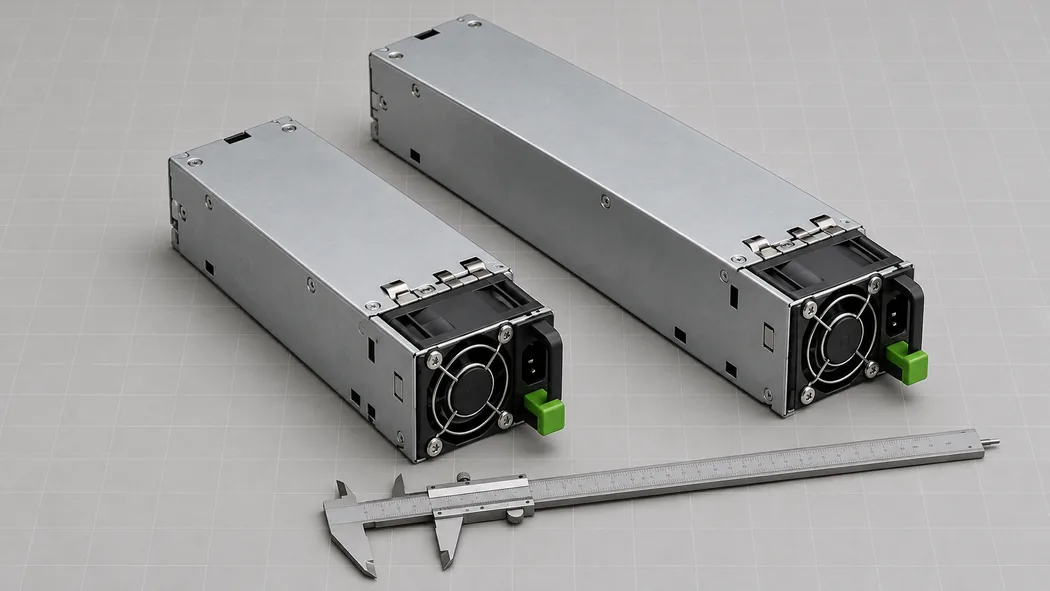
The image illustrates the length issue with generic complete modules; it is not a dimensional drawing of G1236-3000WNA. In a real chassis, measure the distance from the rear insertion plane to the mating connector and identify the required guide and latch geometry. Leave room for the module’s fan, cable plug, handle travel, and removal path. The installed module must remain serviceable without striking adjacent network cables or rack hardware when its latch is released. This is a three-dimensional clearance problem: a nominal body length alone cannot certify the insertion envelope.
Depth also influences what can occupy the space beside and ahead of the PSU. A long module may displace a rear drive bay or require the PDB to sit farther forward. If a platform has two modules, both guided corridors must remain clear when the motherboard, risers, and storage assemblies are installed. The available air path can change as those corridors narrow. A mechanical review should therefore use an assembly drawing or a known-compatible chassis spare listing rather than a generic CRPS silhouette. The critical question is where the output contacts land after the latch locks, not whether the metal housing appears similar in a photograph.
Read 3000 W together with its input tier
The 3000 W marking is a maximum output tier, not a universal output at low-line AC. A published photograph of a G1236-3000WNA rating label shows three conditions: 100–127 V AC with a 1000 W maximum, 200–220 V AC with a 2600 W maximum, and 220–240 V AC or 240 V DC with a 3000 W maximum. The same photographed label associates these tiers with +12.2 V main-output currents of 81 A, 213 A, and 245 A respectively, plus a 12 V, 3 A standby output. This is useful evidence for that labeled specimen; obtain the current rating label and manufacturer document for the exact revision to be installed.
These tiers change practical capacity planning. Suppose a server’s required DC output is 2200 W under a defined peak workload. On the photographed label’s low-line tier, one module’s 1000 W limit would be insufficient. On its 200–220 V tier, the 2600 W maximum leaves a narrower gap to the workload than the headline 3000 W suggests. At 220–240 V, the 3000 W tier may accommodate that assumed load, subject to transients, environmental derating, output distribution, and host approval. This example is a capacity comparison, not a prediction of server consumption or a guarantee of sustained operation. The procurement record should pair the module’s power rating with the actual rack-feed voltage.
For a redundant pair, do not add both nameplate powers and call the result protected capacity. In a 1+1 arrangement, the surviving module must carry the required load after its partner is lost. If two modules receive different AC feeds, apply the rating tier that remains available in the specific failure scenario. A server could run normally with both modules online yet lose redundancy when one feed drops to a lower-voltage source. The failure case is shaped by feed voltage, module rating at that voltage, and host load behavior, not by the number of installed handles.
The module’s inlet and upstream circuit are part of the same question. A 3000 W DC output requires more than 3000 W at the input because conversion is imperfect, but the exact input draw depends on the operating point. Verify the approved cord, connector, PDU outlet, breaker, and regional electrical requirements against the manufacturer documentation. The photographed specimen uses a C20-style inlet; that observation should not be substituted for a controlled inlet specification when ordering a different revision or regional variant.
How the 12.2 V output reaches the host
A +12.2 V main rail is a distribution source. The server’s PDB receives the module output and allocates current to motherboard regulators, storage power, fans, or other approved branches. In a 3000 W class design, the current near the main connector can approach hundreds of amperes at the highest input tier. That makes connector contact resistance, copper geometry, current balancing, and fault isolation consequential. The fact that a supply and host both use a nominal 12 V architecture does not establish matching edge-contact positions, signal pins, standby behavior, or current-share protocol.
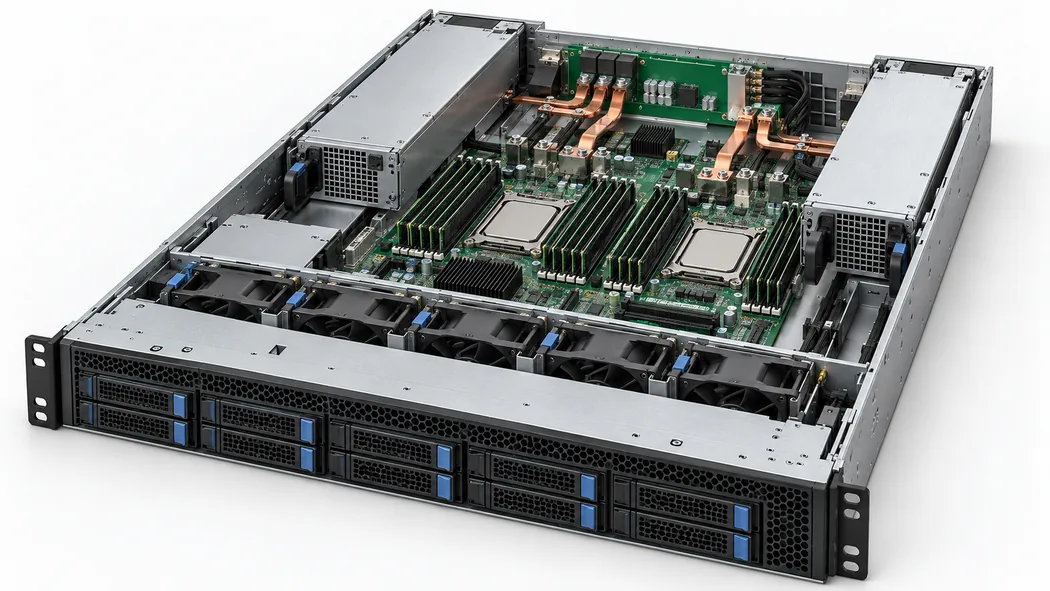
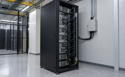
The open-top chassis illustration shows the physical relationship between deep rear modules, distribution hardware, and nearby board space. It is conceptual and does not show a verified G1236 pinout. Before integrating the actual module, obtain the manufacturer’s connector definition and the host PDB drawing. Identify the main output, return, standby, control, sense, management, and chassis-ground paths from those documents. Do not infer pin functions from an image of a gold-finger connector or from a similar G1236 family member.
A high-current bus also makes small resistances visible. At 200 A, an additional 1 milliohm in a shared connection would dissipate 40 W under the simple I-squared-R relationship. That is an illustrative calculation, not a measured resistance or loss for this model. It shows why a mechanically mating connector still needs an electrical rating and thermal assessment at the intended current. The load division between redundant modules can alter current in each connector, while a module failure may move substantially more current through the survivor’s contacts.
The photographed specimen’s label identifies a 12 V standby rail, and Gospower’s series page mentions PMBus support. Neither supplies a revision-specific pin map, command implementation, or BMC compatibility statement for a particular server. Check the host service list and PSU interface document.
The evidence for Titanium efficiency has boundaries
Gospower describes the T265 series as 80 PLUS Titanium. An exact-model 80 PLUS verification report for G1236-3000WNA provides independent test evidence at 230 V nominal and 60 Hz. It reports 96.13% efficiency at the 50% load point and identifies a 3000 W rated output in the tested configuration. That does not mean every installation achieves 96.13%, nor does it establish an efficiency curve at low-line input, unusual ambient temperatures, or a particular server workload. The report’s tested sample and conditions should be read alongside the actual shipping revision and applicable approval records.
At full load, even a highly efficient module rejects heat, and its fan has to move that heat through the server’s designed path. The manufacturer lists fan reversal as a series highlight, but whether a particular chassis supports a given airflow direction must be verified. A supply installed against the intended airflow can recirculate warm air or compete with chassis fans. The long enclosure also occupies more of the internal channel than a 185 mm alternative. Document the required intake and exhaust direction, fan control behavior, and adjacent obstructions for the exact chassis rather than treating the Titanium designation as a thermal design.
Efficiency data cannot substitute for the tiered output rating. A module may be efficient at a tested point yet lack sufficient capacity on lower-voltage input. Establish capacity for the actual feed before examining efficiency and cooling at the expected load.
Use a revision-controlled replacement identity
Evidence outside the catalog shows why exact application identity matters. ASUS spare-parts documentation names G1236-3000WNA as a 3000 W Titanium redundant PSU in a specific server parts list. That establishes a documented use for a listed host and part number, not universal compatibility with every CRPS bay. A replacement order should carry the server model, host part number, PSU manufacturer’s full model and revision, and an approved substitute list where the host vendor provides one. A bare wattage and shortened model family are too ambiguous for a field spare.
Where a product listing conflicts with a manufacturer’s model page, the resolution should be recorded at the purchase boundary. Request a complete-unit photograph, legible rating label, mechanical drawing, controlled datasheet, and host compatibility reference for the offered lot. Check that the label’s input tiers match the site’s feeds. Compare the full insertion depth and contact position with the host’s bay. Match the output and standby definitions to the PDB, and confirm the airflow option and firmware or management expectations with the platform owner. If the supplier proposes a different suffix or revision, repeat the comparison for that exact unit.
For G1236-3000WNA, the strongest public evidence points to a 265 mm T265 module with a +12.2 V main output and a 3000 W maximum at the high-line condition shown on a photographed unit. The shorter 185 mm catalog value remains unresolved for an orderable specimen. Until a controlled document explains it, treating this model as a drop-in replacement for a 185 mm PSU bay would create an avoidable mechanical and procurement risk.