An industrial power supply that appears to have failed may be responding correctly to a fault elsewhere in the cabinet. A dark controller, a flashing DC-OK indicator, or a rail that falls whenever a valve actuates does not identify the failed component. Industrial power supply troubleshooting begins by locating where the voltage changes: at the incoming source, at the converter output, along the distribution wiring, or at a particular load. The pattern during the event matters more than a healthy voltage reading taken several minutes later.
This distinction prevents a common waste of maintenance time. Replacing a supply can temporarily clear an alarm while leaving a loose input connection or intermittent output short untouched. Conversely, blaming a remote sensor cable for a rail that is already unstable at the supply terminals delays a necessary replacement. The following approach concerns accessible, documented test points on an installed industrial AC-DC or DC-DC supply; it is not a procedure for opening a live converter. Qualified personnel should follow the site’s isolation and electrical-safety practices and the specific equipment manual before making measurements or disconnecting a branch.
Start with what the cabinet actually does
A supply with no visible output, one with low voltage under load, and one that repeatedly starts and stops present different evidence. Record which devices fail together and whether the event coincides with a machine action. If the PLC, HMI, and network switch all reset at the same instant, look at their common rail and upstream source. If only a distant I/O module fails while devices near the converter remain powered, the cable, terminal, connector, and return path to that module deserve attention before the supply itself.
Indicator lamps help locate a test point but do not replace a voltage measurement. “DC OK” can refer to the converter’s internal output, a remote-sense condition, or a relay threshold, depending on the model. A green lamp also cannot prove that the remote load receives adequate voltage during a transient. Read the actual legend and manual rather than assigning a universal meaning to a color. Note whether the fault appears immediately at startup, after thermal soak, only with a certain machine cycle, or during a change of upstream power source. These timing clues narrow the electrical event that a meter must capture.
If there is smoke, damaged insulation, a loose energized conductor, or evidence of overheating, stop the normal diagnostic sequence and make the equipment safe. An unexpectedly high output can damage connected controls; do not use a sensitive PLC as the test load while investigating it. Repeatedly cycling a shorted system in hopes that it will restart is not a useful test and can worsen the fault.
No DC output: separate absent input from a converter shutdown
First establish whether the specified input reaches the supply at its actual input terminals during the fault. A breaker handle in the ON position does not establish that line voltage is present there: a fuse, contactor, terminal, or upstream cable can interrupt the path. On a DC-input model, verify polarity and the allowed input range from the model documentation. Measure only with instruments, leads, and procedures appropriate to the circuit. An input that disappears with a machine sequence points upstream; a stable, in-range input alongside a missing DC output directs attention to enable controls, protection behavior, connections, and the converter.
Some industrial supplies include remote ON/OFF or an inhibit input. An open control circuit can make a sound supply appear dead. Others require a specified minimum load or have model-specific startup behavior. Check those conditions against the actual unit before declaring an internal failure. COSEL’s manufacturer troubleshooting guidance lists missing or incorrect AC input, output wiring, remote ON/OFF, and triggered protection among distinct causes of no output; none can be distinguished reliably by the output LED alone.
If isolation is permitted by the machine design, a controlled test with downstream branches disconnected can distinguish a supply unable to establish voltage from a branch that drags it down. This is not permission to unplug live conductors indiscriminately. De-energize and isolate as required, preserve any safety-system dependencies, and avoid backfeeding through parallel supplies or connected devices. If the output returns with the load isolated, investigate the disconnected circuits and startup demand. If it remains absent with correct input and enable conditions, the supply becomes a stronger suspect, although its exact internal defect is not established without manufacturer service procedures.
Low voltage at the load can be a distribution problem
A reading of nominal voltage directly at the supply does not guarantee nominal voltage at the PLC or actuator. Under current, resistance in the positive conductor, return conductor, terminals, fuse holders, and connectors creates voltage drop. Measure across the supply output and then across the affected load terminals under the same operating condition. The difference belongs to the path between those points. A measurement of the positive conductor alone is incomplete if the return is loose or undersized.
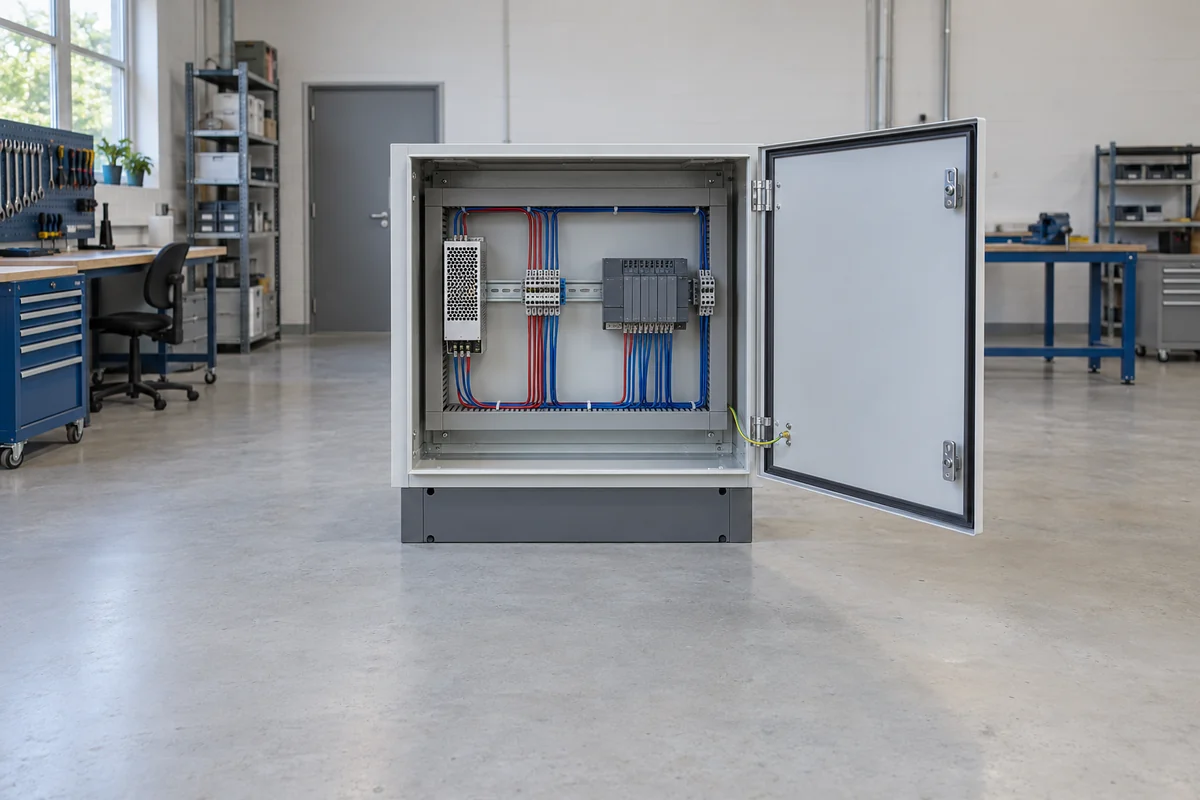
Suppose a cabinet supply stays near its setpoint while a remote device dips only when several solenoids energize. That timing favors distribution impedance or branch loading over a converter that is low at all times. Check terminal torque using the equipment’s documented procedure after safe isolation; look for discoloration, corrosion, damaged ferrules, and overloaded connector contacts. The correct repair may be a terminal, cable route, or branch design rather than a higher-voltage setting. Raising the converter output to mask cable drop can overvoltage nearby loads when the remote load turns off.
Remote sensing complicates the picture. Where a model supports sense leads, it may regulate voltage at the remote connection rather than at its power terminals. An open, reversed, or poorly connected sense pair can cause unexpected output behavior. Never bridge or rewire sense pins from a generic diagram: their allowed connection and protection behavior are model-specific. COSEL explicitly includes output-wire voltage drop and remote-sense oscillation in its abnormal-output guidance. The location of the measurement therefore belongs in every diagnosis, not just the number on the display.
Repeated start-stop cycles point toward load and protection behavior
A supply that starts, collapses, waits, and tries again may be operating a hiccup-style overcurrent protection scheme. Other units use constant-current limiting, foldback, latching shutdown, or another documented response. A pulsing output does not by itself prove that the converter is defective. Identify the exact model’s protection description and compare the observed rhythm with it. If the behavior starts after a new load is added, a branch is energized, or a motor brake releases, inspect that event rather than assuming the nominal steady current is the whole demand.
A shorted cable or device can exceed the protection threshold. So can a large capacitive input or several loads starting simultaneously even when their established current is within the continuous rating. Separate the branch only under a safe, approved procedure, then restore loads in a controlled sequence. The branch whose connection reproduces the collapse localizes the problem, but it does not yet distinguish a wiring fault from legitimate inrush or an undersized converter. Look at branch current over the startup interval, protective-device action, and the loads’ own inrush specifications.
Parallel and redundant systems need a further distinction. A failed isolation device or current-sharing arrangement can let one supply or branch pull down a common bus. Test the arrangement as the manufacturer specifies; do not treat two supplies connected to the same output as interchangeable standalone units. A healthy module removed from a redundant pair can change the load on the survivor, so a test performed in one-module operation may intentionally expose a capacity limit rather than an unexpected fault. Preserve the designed fault boundary while diagnosing it.
Intermittent resets need measurements that survive the event
A handheld meter may show normal voltage before and after a five-millisecond disturbance. It has not proved that the rail remained healthy between those readings. Capture the supply input, converter output, and, when practical, voltage at the affected device across the operating event. A recorder or oscilloscope can reveal whether an upstream dip precedes the output collapse, whether output current rises first, or whether only the remote load voltage falls. These sequences lead to different repairs.
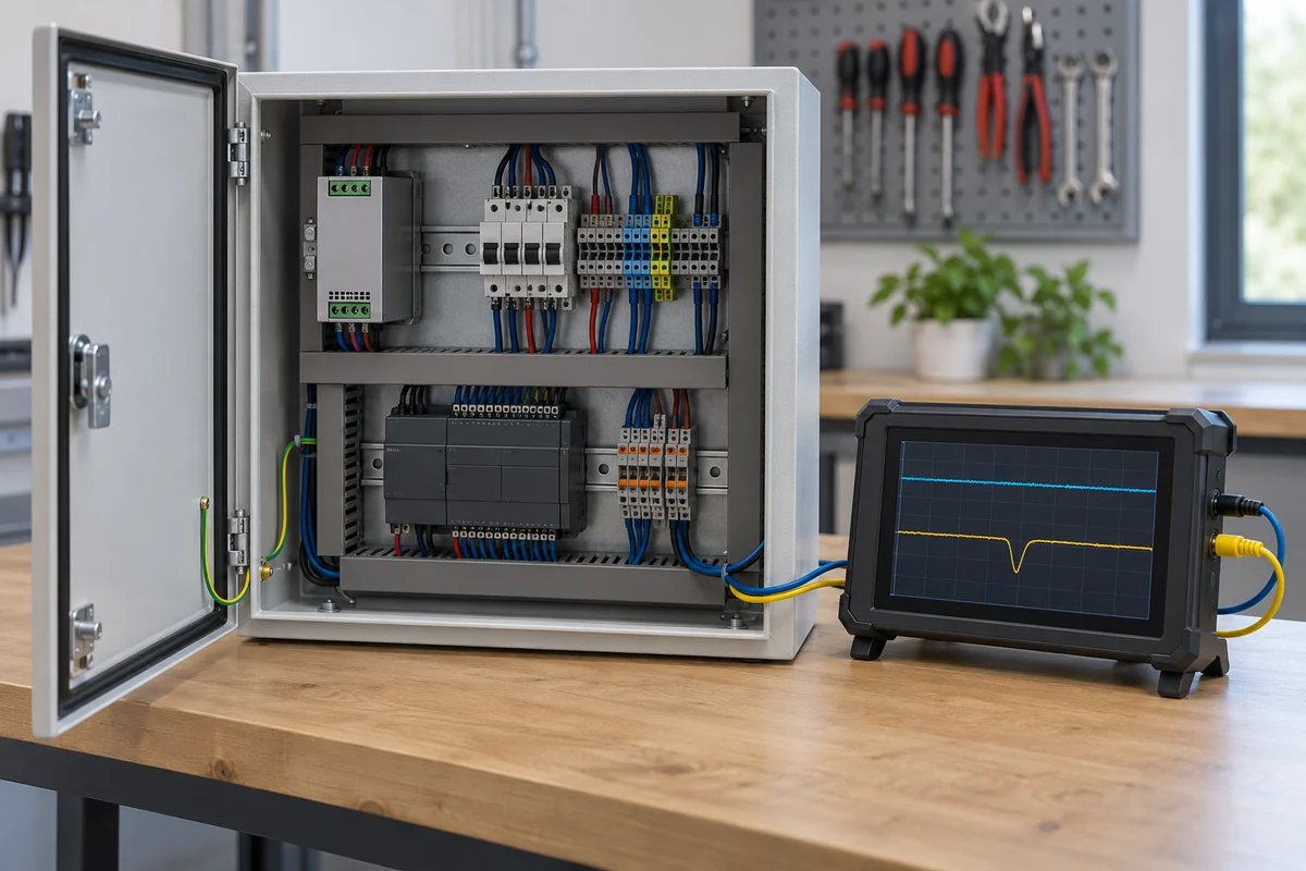
Fluke’s DC power-supply troubleshooting example illustrates why simultaneous or time-correlated measurements outperform a normal spot reading: its case distinguishes an input-voltage disturbance from excessive output current by recording behavior over time. That is a method, not a universal threshold for industrial supplies. Use isolated or differential measurement techniques where the circuit requires them; connecting an ordinary oscilloscope ground to an energized nonisolated point can create a hazardous short. The tool and probe arrangement must be suitable for the circuit category and the site’s electrical rules.
Capture enough context around the event to identify cause and effect. If line voltage sags first while load current is unchanged, examine the upstream feed, contactor, generator transition, or shared machine load. If output current surges before voltage collapses while the input remains stable, examine the downstream branch and startup sequence. If input and measured load stay steady but the supply output wanders after prolonged operation, thermal behavior or an internal converter problem becomes more plausible. A single capture from only one location may show the symptom without locating its origin.
Heat, noise, and ripple require different interpretations
Temperature-dependent faults often emerge after the cabinet has been operating for some time. Record the supply’s inlet-air condition, not merely room temperature outside a sealed panel. Check for blocked ventilation openings, adjacent heat sources, failed cabinet fans, dust accumulation, and spacing inconsistent with the exact product instructions. A supply may deliver the expected voltage when cool and limit or shut down after thermal soak. Do not infer a universal permissible temperature or derating curve from its industrial label; those values belong to its datasheet and installation orientation.
“Noisy output” also needs a defined measurement. A digital meter reading slightly below nominal does not establish excessive ripple. Use a suitable instrument and measurement bandwidth, compare against the unit’s documented ripple/noise specification, and account for where the probe and return connect. Long leads can pick up switching noise or reflect voltage drop that is not present at the converter terminals. If an analog sensor is unstable while the main rail appears steady, compare its local supply and ground with the main bus during the disturbance. Wiring, shielding, and shared return currents can matter as much as the converter’s own output quality.
Audible ticking can come from repeated startup attempts; a fan change can accompany higher load or cabinet temperature. Neither identifies the failed part. A discolored output terminal is evidence of local heating, but high contact resistance rather than converter electronics may be responsible. Resolve that path before reusing a damaged connector.
Use the fault location to choose the repair
A genuinely failed converter is one possible outcome, not the starting assumption. If its specified input and control state remain correct, its output is absent or outside its documented behavior under an appropriate known load, and downstream faults have been isolated safely, replacement or manufacturer service is justified. An upstream sag calls for source or switching-path work. Voltage that is sound at the supply but poor at the remote device calls for distribution repair. A current spike tied to one branch calls for load, short-circuit, or startup analysis. The same alarm lamp can accompany all four cases.
After correction, repeat the operating event while observing the relevant test points. A no-load check is insufficient if the symptom occurred during actuator startup or after an hour in a hot enclosure. Keep locations and operating state attached to the finding: “24 V at the supply” and “24 V at the remote controller under load” are different statements. That distinction makes the diagnosis useful when the next shift encounters the machine.